Can't keep up. Grounded grid can't be different in the internal functioning of a valve from any other config. Bird on a wire.
ch
ch
I keep coming back to Jan's thoughts in post #240 about the relation of the integrator to stability. Is there a threshold area, some non-linear transition, between our ability to recognize the (whatever) differences between small, local, "tight" feedback loops, for whatever reason, and longer, still very fricking short delays, but bigger time constants, loops?
Stability and integration time are linearly related in a simple single pole integrating system, and both are independent of delay (for audio modelling purposes). My question is: could the (ignored, for usually a very good reason) propagation time be significant to the (possibly even true!) observations about local degeneration, and the easily observable fact of triode curves approaching the Child simplification (that assumes infinite parallel planes, not space charge limited, etc.)
Might be nowhere to go with it, but even a way to calc the contribution of some tiny time delay to the integrators' output is so difficult that I despair of understanding it.
"Camelot!".
"Camelot!"
"It's only a model."
All good fortune,
Chris
No idea if this answers the question, but phase-locked loops are often designed with a simple continuous-time model that neglects the delay of the phase detector - which is related to the reference frequency, and is typically many decades larger than the transmission line delays and transition times in an amplifier. As long as the bandwidth is at least ten times smaller than the reference frequency, the results are close to the real behaviour of the PLL.
Mixed discrete-time and continuous-time control systems can be designed as if they were continuous-time systems if the bandwidth is much smaller than the reciprocal of the delay around the loop, but a more accurate approach that also works when this condition is not met is to transform the continuous-time parts into equivalent discrete-time parts using an impulse-invariant transform. The whole loop can then be designed in the z domain.
Well there`s always be some solution , even for audio application , for so many RF linear application it is already solved even in Ghz range ....driving a cathode is not the easiest thing to do...
Marcel, Whoosh! for me of course, but that does sound like the same issue that puzzles me, although I have no clue about z domains or such. Strictly plebeian, all strain, no brain.
Could you comment on the possibility/difficulty of wrapping time delays into the Taylor series (propagation ignored) FFBP model and your thoughts about any possible significance? Obviously the second is fraught with peril, so ignore if appropriate.
To phrase it another way, how difficult is it to define the difference in instantaneous (signal) voltage between a model with and one without propagation time?
(very) Much thanks for any thoughts,
Chris
You're right, there's no difference in the internal tube functioning.Can't keep up. Grounded grid can't be different in the internal functioning of a valve from any other config. Bird on a wire.
ch
But this is the external circuit, and that determines the voltages on the tube terminals and the currents into/out of them.
It 'works' determined by, for instance, Vgk. Ground the g, drive the k, same difference.
The tube isn't any wiser either way, but we are ;-).
Edit: the internal Cag fb works by a current flowing from Va through that cap to the grid terminal.
If there is a grid impedance, that current will generate a grid voltage across that impedance (Ohm's Law and all that).
How to avoid that? make that impedance zero by grounding the grid (and driving the cathode).
Very straighforward electronic design.
Jan
Last edited:
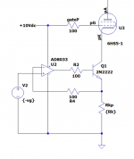
At first blush, it's a simple cascode. Ia would be exactly equal to Ik.
In this respect, I was wondering about the posited internal feedback in a triode. I suspect that could be a whole new nebulous thread for some adventuresome soul to pursue. If we're lucky, it wouldn't effect the "infernal feedback" issue in triodes, but who ever gets that lucky in life?
For me, the hardest part of learning, at my age (less than you! Geezer.) is figuring how to ask the question. We share Le Gai Savoir with others on this thread.
Much thanks, as always,
Chris
ps: and Ik is a linear function of input violtage.
Last edited:
Marcel, Whoosh! for me of course, but that does sound like the same issue that puzzles me, although I have no clue about z domains or such. Strictly plebeian, all strain, no brain.
The z transform and z domain are a mathematical trick to change linear time-invariant difference equations into much simpler rational equations, similar to what is done with the Laplace transform and s domain for differential equations.
Could you comment on the possibility/difficulty of wrapping time delays into the Taylor series (propagation ignored) FFBP model and your thoughts about any possible significance? Obviously the second is fraught with peril, so ignore if appropriate.
To phrase it another way, how difficult is it to define the difference in instantaneous (signal) voltage between a model with and one without propagation time?
(very) Much thanks for any thoughts,
Chris
I see, that means I've been answering the wrong question. In general, non-linear difference and differential equations are difficult to solve. Often they are even impossible to solve analytically and can only be numerically approximated. My gut feeling is that delays much smaller than the reciprocal of the loop bandwidth won't have much of an impact on the distortion, but my mathematical skills are insufficient to prove that.
The equivalent of the Taylor series for dynamic systems is the Volterra series. The only thing I know about Volterra series is that they exist.

Yes. And if I would give you this thing inside a black box with only Vin and Ia accessible, you'd say there's a pentode inside the box.At first blush, it's a simple cascode. Ia would be exactly equal to Ik.
In this respect, I was wondering about the posited internal feedback in a triode. I suspect that could be a whole new nebulous thread for some adventuresome soul to pursue. If we're lucky, it wouldn't effect the "infernal feedback" issue in triodes, but who ever gets that lucky in life?
For me, the hardest part of learning, at my age (less than you! Geezer.) is figuring how to ask the question. We share Le Gai Savoir with others on this thread.
Much thanks, as always,
Chris
ps: and Ik is a linear function of input violtage.
Jan
Marcel, Thank you very much. I'm, or course, expecting too much to hope that someone could translate such a highly abstract thing into a seat-of-the-pants description that even I could understand without too much effort. The working model is what interests me, I've no time for reality! Tick, tick.
Much thanks, as always,
Chris
Much thanks, as always,
Chris
Jan, Can I measure the harmonic spectrum? And if so, could I tell triode or pentode? One possible clue might be the rate of rise of distortion products with signal level, as second order and third order products increase at different rates. But I get your point, context is everything.
Much thanks, as always,
Chris
Much thanks, as always,
Chris
On the bench is a 6SF5/7591 pentode mode SE with slightly over 20 dB of feedback. The initial design employed the traditional RC degeneration from the OPT secondary. The current version uses series RC from output stage plate to input stage cathode, about as 'fast' as realisable with a two stage amp. Distortion wise they measure close save for some variances (from memory) in harmonic numbers over 10 and greater than 90 dB down. The frequency response of the traditional FB was flat past 100 kHz and the internal loop about 0.5 dB down at 20 kHz with a gentle slope afterwards and no peaking. Response is flat at the plate so the fall off apparently represents the secondary's behaviour.I'm particularly interested in finding any possible mechanism that would distinguish very local, very fast, very low time constant, very small delay feedbacks from slightly larger delays....
Due for revisit and the amp will be laid out to support either but audibly the PK internal FB version was a 'what am I hearing' experience. Much better than the external loop.
BTW, even with the 6SF5's high plate impedance Schade was a no-go, suppressing the dominant second but accentuating everything above.
Could you, please make a drawing? I have difficulties visualizing it! I have two EL156 that might use your ideea.The current version uses series RC from output stage plate to input stage cathode, about as 'fast' as realisable with a two stage amp.
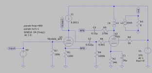
Short OT; sure, schematic below. The 6SF5 is a glass envelope equiv to the 6F5 used in this sim. OPT is a 5k.
Depending on dB of desired feedback and input stage biasing/tube type it should be possible to eliminate the series capacitor by factoring in the P-K DC current injection of the feedback resistor and scaling the 6F5's cathode resistance accordingly to maintain constant G-K voltage. However increasing FB by reducing the plate-cathode resistor injects more DC current and forces greater reductions of the input stage cathode resistor, thereby reducing the level of feedback achieved by lowering the P-K resistor in the first place. I tried it, it works but I couldn't achieve the desired overall level of feedback with these tubes. Interestingly I didn't note any obvious audible change on the bench with the cap, maybe because it's in series with 270k?
This FB circuit does 1 watt at about ~ 0.15% dominant second with 3rd around 0.03% and everything higher ~90 dB down min. Pleased enough with the topology that the next SE might attempt an 828.
Attachments
I had similar experience when cloning Luxman Cl34 phono preamp.The original used op amps for DC offset control and I realized it was useless...Interestingly I didn't note any obvious audible change on the bench with the cap, maybe because it's in series with 270k?
As often than not, there is a capacitor connected in parallel with the negative feedback resistor that comes from the output transformer secondary to the negative feedback node.
That nfb cap is sized just large enough to give a little more phase margin, but not to change the amplitude response.
It is a shelf filter whose purpose is to reduce the gain to zero before phase shift reaches 180 degrees.
Hi, I'm rather late to the game here, but this is the most recent negative feedback thread I can find.
This may be a very simple question with a very complex answer (to a novice), but I'll ask anyway. 😁
1) When is it prudent to include this capacitor and why is it not always there?
2) How is the size determined correctly?
3) Does anyone have a good schematic for me to try to learn this?
I always very strongly recommend to folk wanting to understand feedback to start with an op-amp model and the stick-fiqure models by Hendrik Bode, done back before the War. His model applies universally and, once accepted, gives us a solid handle on the issues involved in stability. Or, if that's the goal, instability! (Which, for a linear oscillator, also requires stability!).
There is no cookbook answer to your question, but there is an elegant understanding available. Modeling feedback, like everything else, means simplifying, and this elegant model will allow you to understand all variations of "feedback". Without a good model we have only Lore, a weak cousin.
All good fortune,
Chris
1) There are some exceptional cases where a small capacitor across the feedback resistor may degrade stability no matter how you size it, but normally it improves stability with no reduction of the loop gain. The only disadvantage I know of, is that it couples RF interference picked up by the loudspeaker wires to the input stage, but there are solutions to that, such as a first-order series filter at the amplifier output (as proposed by A. N. Thiele many years ago).
2) There are many essentially equivalent ways to assess/design the small-signal stability of a feedback system: the Nyquist stability criterium, Bode plots, looking at the small-signal step response and checking for ringing or oscillations, root loci, calculating the characteristic equation and equating its coefficients to desirable values...
Bode plots are popular for calculations because they are relatively simple and intuitive and give an impression of how effective the feedback is.
Looking at small-signal step responses is convenient for measurements (and simulations). You just have to make sure there is no filter in the path that makes high-frequency ringing hard to see.
Small-signal stability doesn't guarantee large-signal stability and I know no simple theoretical method to assess large-signal stability. The pragmatic approach is to design for small-signal stability and then measure (or first simulate and then measure) what happens during start up and during recovery from clipping.
Vacuum valve amplifiers do give DIYers some advantages here, not the least of which is the simple ability to operate in class A without any special drama or detailed knowledge of semi-con internal heat paths and Special Dispensation Safe Operating Areas. Professionals are forced to learn all that, but DIYers can live in blissful ignorance (like me). Class A makes the direction of so many issues monotonic with signal level that those issues tend to fade away.
Examples of the great advantages of Class A are: minimized coupling through a common power supply to earlier stages (presumably Class A themselves), monotonic increase in OPT (output transformer) primary/magnetizing inductance with increasing signal level (place the output valves' source resistance x OPT primary inductance pole below the dominant LF pole and stability increases with signal level), and the elimination of the "transconductance-halving" at the transition into AB mode.
So I say Yeah for Class A,
Chris
And for the ancient idea of vacuum valves. Who knew? Running hot is cool again.
MarcelvdG,
A generalization about vacuum tube amplifiers with an output transformer; and no local negative feedback:
Consider a global negative feedback resistor from the amplifier output to the earlier amplifier circuitry's feedback node.
Then if we connect a compensation capacitor across that feedback resistor, we Do have a change in loop gain (at higher frequencies).
Loop gain is not a fixed number, because:
We have a low frequency response roll off, before applying global negative feedback.
We have a high frequency response roll off, before applying global negative feedback.
And then, with those high and low frequency rollo offs, when we apply global negative feedback (we have loop gain that varies with frequency).
Modeling stability of a vacuum tube amplifier that uses global negative feedback . . .
In order for the simulation to be accurate, one very important requirement is to have correct and full parameters of the output transformer.
Just my opinions
Last edited:
- Home
- Amplifiers
- Tubes / Valves
- Negative Feedback