Just wondering if anyone has used negative feedback to the differential pair used as CC drivers for the power tubes. I don't mean the phase inverter configuration, but the long tailed pair with two in- and two outputs.
Could you upload the schematic which shows us what you've said? Nfb could make the amp design complicated with phase relationship of each input signal, if wrong phase feeded to the output, positive feedback is what you'll get.
Doing this at the driver stage could cause problems with common-mode distortion, unless you arranged negative feedback to both sides. CM distortion is less of a problem when NFB is applied at the input stage, as signal levels are much lower. Applying NFB to both sides carries the risk of extra phase shift, as you might no longer have a minimum phase system.
Just wondering if anyone has used negative feedback to the differential pair used as CC drivers for the power tubes. I don't mean the phase inverter configuration, but the long tailed pair with two in- and two outputs.
It's done frequently in the Circlotron OTL topology. No different, really, than how it's done with SS op-amps. The main thing to watch out for is that you buffer inputs that could be connected to different source impedances, as these add to the Rs resistor(s) and can unbalance/change the level of NFB you've designed for. It's not a prob with SS op-amps since these already use buffered output stages that have very low impedances.
Thanks for all the info! I'll look into the Circlotron topology. I understand the necessity for balanced (buffered) sources, but for some reason, the workings of global NFB to the LTP elude me...
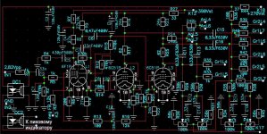
To make sure we're all talking about the same thing, I sketched up a schematic of what's in my head, as Jehan suggested. Is it still viable??

To make sure we're all talking about the same thing, I sketched up a schematic of what's in my head, as Jehan suggested. Is it still viable??
No. Something like that is sometimes used in guitar amps, but there the aim is not fidelity but controlled distortion. The problem is that the feedback is applied in common-mode to a differential-mode stage. You should instead put the feedback on the second LTP grid. Then to avoid common-mode distortion use a CCS tail.
I suggest to separate the driver cathodes by removing its tail, then put a remote sensing negative feedback from output transformer's secondary legs to driver cathodes. I think it would sounds fabolous.
try r5 and r10 being doubles as each triode have its own r5&r10.
then tie a 100k pot between where the nf was one on pin1 and one on pin3 of pot. tie pin 2 of pot (wiper) to the negative FB network.
adjust for gain linearity.
then tie a 100k pot between where the nf was one on pin1 and one on pin3 of pot. tie pin 2 of pot (wiper) to the negative FB network.
adjust for gain linearity.
If you can find,beg or borrow or just wait for someone who still has an ''RCA Receiving Tube Manual" to post the circuit;then the Class AB1,50 Watt circuit may be your answer.Feedback was applied from the O/P valve anodes to the anodes of the differential drivers and to the cathodes.The result of this feedback enabled the O/P valves to present a low source impedance to the transformer as well as improved linearity.This type of feedback was used in many early ccts that RCA published and gradually disappeared with the growing popularity of the ultra linear topology.
Also David Berning employed plate (from OP tubes) to cathode feedback in (some of) his G2 driven amplifiers. These schematics can be downloaded from his site, and maybe it helps to understand the working of balanced feedback.
If you can find,beg or borrow or just wait for someone who still has an ''RCA Receiving Tube Manual" to post the circuit;then the Class AB1,50 Watt circuit may be your answer.
I think SY posted this in a thread:
http://www.bunkerofdoom.com/tubes/rc25/c09b.gif
If you want the whole stuff look at pmilletts site:
http://www.pmillett.com/file_downloads/RCA_HiFi.pdf
Page 14 is what you want...
hope this helps
- Status
- Not open for further replies.
- Home
- Amplifiers
- Tubes / Valves
- Negative feedback to differential pair driver