Hello,
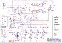
I have got Primaluna One amplifier (schematics in attachment), and wondering, how it will sound without feedback or with minimal feedback... Can somebody please help me answer these questions:
- is it safe to completely remove feedback loop?
- which resistor value (R16a in top right corner) to use to minimize feedback to let's say 1/4, 1/10 of default one?
Thank you in advance.
Kamil
Attachments
An amplifier designed to use significant feedback will have poorer performance with little or no feedback. You should expect: higher distortion, higher output impedance (so lumpy frequency response with most loudspeakers), narrower bandwidth, more noise, more hum. However, there is no accounting for taste, so some people might prefer the sound from this degraded performance.
Feedback is set by R16a, R16 (and C12) and R2. R2 also sets the bias for the first stage. C12 helps maintain loop stability.
Feedback is set by R16a, R16 (and C12) and R2. R2 also sets the bias for the first stage. C12 helps maintain loop stability.
An ultralinear design with no loop feedback will, as DF96 pointed out, higher output impedance. This will show up on a lot of speakers as "uncontrolled" bass. Higher distortion too.
If you want to experiment - triode strap the output, remove and or reduce the negative feedback, and see what the results are. It may be more "pleasing" to the ear or maybe not.
If you want to experiment - triode strap the output, remove and or reduce the negative feedback, and see what the results are. It may be more "pleasing" to the ear or maybe not.
DF96: Yes, of course, you are right... there would be this difference in measurable parameters and much of them will be worse than before. I used to have SET amplifier, which THD and other parameters surely is worse than Primaluna's... but sound and musicality of SET is another thing 🙂 So I would like to try it and hear how feedback affects final sound of amplifier... And also, you can see in Manley or Cary amplifiers, that they have option to lower or even turn of feedback...
Good advice from DF96. Nothing will improve by removing the feedback loop, you will also end up with more overall gain from the amplifier which might also cause you problems.
While i agree with post #3 regarding the necessity to switch to triode operation before removing feedback i would also caution against doing this. It seems the EL34 are getting close to 450v at their anodes and a triode conversion at such high voltage will severely shorten their lives.
Hi there kamilrakyta,
Why does R7 and R8 have different values? isn't that supposed to be a LTP?
Regards,
Silviu
Why does R7 and R8 have different values? isn't that supposed to be a LTP?
Regards,
Silviu
Hi Kamil,
Sorry may I ask how you manage to get the schematics ?
Im trying to get a set for my Dialogue 7.
Thanks
Sorry may I ask how you manage to get the schematics ?
Im trying to get a set for my Dialogue 7.
Thanks
Ha! Here we have it! This isn't a high fidelity amplifier, but an effects device instead!
Best regards!
Best regards!
Hi there Kay Pirinha,
Exactly my thought. Looks like a even harmonic generator trick, same as on guitar amps.
Regards,
Silviu
Exactly my thought. Looks like a even harmonic generator trick, same as on guitar amps.
Regards,
Silviu
Last edited:
This isn't a high fidelity amplifier, but an effects device instead!
I would not word it as strongly. If this is not an error it is just an attempt to maintain a distortion spectrum where the even components are not unnaturally depressed as a perfect PP topology would cause them to be. In the large picture it is just a trifle, a mild timbral manipulation.
Actually I think it's very clever of the designer to do this. Aren't we all diyers manipulating parts to get good sound ? Great explanation Analog_Sa.
Norman Crowhurst wrote an article on optimizing feedback. It involves removing the phase compensating capacitor from the feedback loop and adding a small value cap. from the input tube plate to ground to reduce high frequency response. If removing cap. results in instability will require reducing value of the feedback resistor. Requires 'scope with X/Y function to determine value of the input shunt cap. Crowhurst notes response is typically down 3dB@20kHz after modification, but claims amp sounds better.
Hi Kamil,
Sorry may I ask how you manage to get the schematics ?
Im trying to get a set for my Dialogue 7.
Thanks
Hello, sorry, schematics to Dialogue series probably couldn't be found online... my source is obvious hifiengine.com...
Very interesting, thanks. I feel -3db @20kHz is a bit borderline, but still interesting. Unlike the nfb cap, this one has to be rated at high voltage, which is not very convenient.Norman Crowhurst wrote an article on optimizing feedback.
Norman Crowhurst wrote an article on optimizing feedback. It involves removing the phase compensating capacitor from the feedback loop and adding a small value cap. from the input tube plate to ground to reduce high frequency response. If removing cap. results in instability will require reducing value of the feedback resistor. Requires 'scope with X/Y function to determine value of the input shunt cap. Crowhurst notes response is typically down 3dB@20kHz after modification, but claims amp sounds better.
It seem to be this article: https://groups.io/g/funwithtubes/attachment/61521/0/Optimize Audiocraft 4-57.pdf
@savu, Kay - which part in the schematic is the even harmonic generator? All of it? The autobias part?
@kamilrakyta, a trick I've played is not to disconnect the negative feedback, but to move it to the far end of your speaker cables. If you're using FR speakers, better yet connect it right to the speaker terminals.
To do that, you'd put a 10 ohm in series with the output tranny ground connection, another 10 ohm in series with the 1K feedback resistor. Then connect - via another audio cable - speaker negative to amplifier ground, speaker positive to 10/1k junction.
The 10 ohms are just fall back protection, in case your feedback wiring becomes accidentally disconnected. Might as well put all the negative feedback to best use by extending its global reach to include the speaker cables.
@ analog - there's a nice write up by Kenwood at http://www.cieri.net/Documenti/Kenwood/Documenti tecnici/Kenwood - Sigma-Drive Technical Guide.pdf for those who'd like to read their claims...
Regarding the 2nd harmonic generator, I'll put my ignorance on the table for all to see - it's the 12AX7 paralleled triode elements at the input stage.
Regarding the 2nd harmonic generator, I'll put my ignorance on the table for all to see - it's the 12AX7 paralleled triode elements at the input stage.
Regarding the 2nd harmonic generator, I'll put my ignorance on the table for all to see - it's the 12AX7 paralleled triode elements at the input stage.
I'm not sure, but I think that it is R7 and R8 resistors, which are not same... because it is in invertor stage and it develops different voltage for positive and negative voltage. And this kind of distorsion is even harmonic...
- Home
- Amplifiers
- Tubes / Valves
- Negative feedback loop in Primaluna One