When I got this amp the PS FET's on one side were all blown. I replaced all the PS FET's,the PS MPSA06's and MPSA56's, all output transistors, all electrolytic capacitors and the 494. The amp powers up and plays but it the sound is distorted and not producing full sound output/power. I pulled the muting circuit transistors to see if it would make a change and it had no effect on it.
A distortion problem is difficult to diagnose without seeing the signal.
Are both rails equal?
Is both ±regulated voltage present at all op-amps?
Are both channels equally distorted?
Are both rails equal?
Is both ±regulated voltage present at all op-amps?
Are both channels equally distorted?
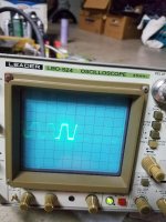
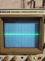
It seems my scope is a little temperamental, sometimes I can get a
non-distorted waveform out of it, other times not. Before I bought my scope it sat in someones storage unit for years. Thinking possibly some of the plug connections inside it are oxidized. Anyway, I was messing with it and was able to get the waveform in the photo (the best photo I could get of the screen).
During the above process I noticed the two voltage regulators (circled in the photo) are getting hot.
Both rails are equal.
Both channels are equally distorted.
As to testing the op-amps, will you give me more direction on how to do so?
Attachments

Post a photo of the distorted waveform. If you don't have a signal generator, use one of these:
http://www.bcae1.com/temp/100hz300seconds.zip
http://www.bcae1.com/temp/80hz800hz8khztestsignal01.zip
http://www.bcae1.com/temp/100hz300seconds.zip
http://www.bcae1.com/temp/80hz800hz8khztestsignal01.zip
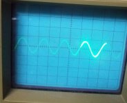
I'll use the test tones you provided and post a photo. The photo I posted is of the waveform the amp is producing using a 50hz test tone.
With the scope set the same as when you took the post 7 photo, how far up does the scope trace deflect if you touch the probe to the rail voltage?
What is the rail voltage, measured with a multimeter? black probe on the RCA shield
What is the rail voltage, measured with a multimeter? black probe on the RCA shield
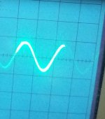
So... the amp is clipping at about 10v with a rail voltage of 30+v?
Do you have ±15v on the power supply pins of all of the op-amps?
Do you have ±15v on the power supply pins of all of the op-amps?
If I were to say the amp is clipping at about 10v, I would be guessing but it sounds about right.
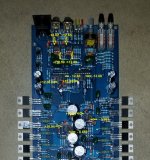
I do not have +/- 15v on the power supply pins of any of the op-amps. Given that I tested the right pins... See attached photo for the pins I tested and voltages.
I do not have +/- 15v on the power supply pins of any of the op-amps. Given that I tested the right pins... See attached photo for the pins I tested and voltages.
Attachments
±15 is sort of a generic term. I can't remember which amps use ±10 or ±18 or anything in-between.
You're not pointing to the power supply pins of the NE5534s.
You're not pointing to the power supply pins of the NE5534s.
Will you point out the power supply pins for me? I'm apparently not reading the data sheet for the NE5532N correctly.
- Status
- Not open for further replies.
- Home
- General Interest
- Car Audio
- Needing help repairing an Orion HCCA 250 Digital Reference