This project has been really challenging me.
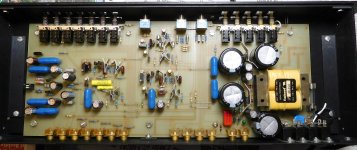
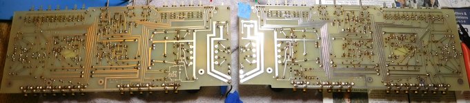
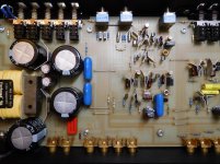
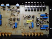
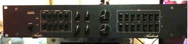
It's a very interesting design with really high-quality components, but really difficult to work on, because it is two mirrored channel boards that sandwich a central chassis backplane. Access to the bottom of the boards must be made by completely opening it up like opening a sandwich. I am guessing Julius knew how to test the boards in situ, but any repairs require opening it up completely. The unit had been repaired twice by Julius, the second time it appears, with one board being replaced. I haven't been able to find a schematic.
When I got it from my brother, who bought it new from Julius, it had blown out his Otez amp, and in testing I found that it had high DC offset in one channel. I found it also had some electrolytic caps that had leaked onto one board, and one sealed Clarostat volume pot with a damaged trace. There were some flux accumulations and a few dodgy solder joints. It appears the pots, with their board mounting legs, are long out of production, so I'm still trying to determine the best fix for that pot, but only if I can fix the larger problem.
I started with the caps, replacing all of the electrolytics with then went through and measured and tested every component I could test. I cleaned up solder joints, removed flux, and cleaned jacks and switches. I have one channel working perfectly, but the other channel still has high enough DC to trigger the protection in one of my amps, and blow the rail fuse in my other amp.
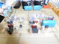
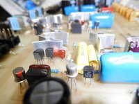
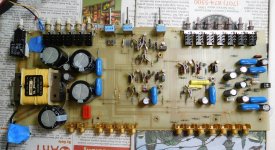
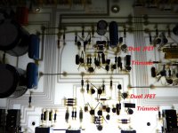
I have not figured out how identify, let alone troubleshoot the JFETs, and what voltages they should be seeing. I'm hoping it's just a matter of adjusting the trimmers on the boards, but I'm not sure if I'm taking voltage readings at the right points (or transistor legs), or even if I'm upsetting voltages on the JFETs with my Fluke meter. Also, it looks like some of the metal can transistors may have been house parts for Audire because many don't have part numbers that show up online anywhere; some look like they had original mfr. numbers, but were printed over with house part numbers.
I am not a trained tech or engineer, but electronics has been my hobby for 50 years, and I've built many tube guitar amps, repaired guitar amps, built tube mono block audio amps, and have been teaching myself (with much reading from you folks here at diyaudio) how to service, repair and upgrade solid state audio gear. I've bought and am reading a half dozen books on audio design, troubleshooting, and repair, but my troubleshooting skills are just not up to the task of tracking down one remaining problem with this beautiful preamp.
It is such a rare and interesting preamp with great personal history for my brother, that I'd really like to fix it, and improve my abilities at the same time. I've attached some photos and can post more.
Thank you
It's a very interesting design with really high-quality components, but really difficult to work on, because it is two mirrored channel boards that sandwich a central chassis backplane. Access to the bottom of the boards must be made by completely opening it up like opening a sandwich. I am guessing Julius knew how to test the boards in situ, but any repairs require opening it up completely. The unit had been repaired twice by Julius, the second time it appears, with one board being replaced. I haven't been able to find a schematic.
When I got it from my brother, who bought it new from Julius, it had blown out his Otez amp, and in testing I found that it had high DC offset in one channel. I found it also had some electrolytic caps that had leaked onto one board, and one sealed Clarostat volume pot with a damaged trace. There were some flux accumulations and a few dodgy solder joints. It appears the pots, with their board mounting legs, are long out of production, so I'm still trying to determine the best fix for that pot, but only if I can fix the larger problem.
I started with the caps, replacing all of the electrolytics with then went through and measured and tested every component I could test. I cleaned up solder joints, removed flux, and cleaned jacks and switches. I have one channel working perfectly, but the other channel still has high enough DC to trigger the protection in one of my amps, and blow the rail fuse in my other amp.
I have not figured out how identify, let alone troubleshoot the JFETs, and what voltages they should be seeing. I'm hoping it's just a matter of adjusting the trimmers on the boards, but I'm not sure if I'm taking voltage readings at the right points (or transistor legs), or even if I'm upsetting voltages on the JFETs with my Fluke meter. Also, it looks like some of the metal can transistors may have been house parts for Audire because many don't have part numbers that show up online anywhere; some look like they had original mfr. numbers, but were printed over with house part numbers.
I am not a trained tech or engineer, but electronics has been my hobby for 50 years, and I've built many tube guitar amps, repaired guitar amps, built tube mono block audio amps, and have been teaching myself (with much reading from you folks here at diyaudio) how to service, repair and upgrade solid state audio gear. I've bought and am reading a half dozen books on audio design, troubleshooting, and repair, but my troubleshooting skills are just not up to the task of tracking down one remaining problem with this beautiful preamp.
It is such a rare and interesting preamp with great personal history for my brother, that I'd really like to fix it, and improve my abilities at the same time. I've attached some photos and can post more.
Thank you
Attachments
Last edited:
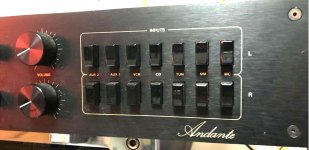
Thank you, Chris. I found that back in December 2018, but it is a later design using op amps instead of discrete JFETs, among other differences, including no tone controls, and I suspect the problem with DC offset in this unit is related to the tone control circuit.
That is based on a couple of times when it was connected to an amp and powered up, I switched the tone controls either out or in, and the amp protection would pop on the right channel.
Is it possible to get reliable voltage readings from JFETs without the loading from my Fluke causing inaccuracy?
Cheers,
Greg
Hi Greg,
Yup, no problem with JFets. If you're worried, you can use your oscilloscope. The voltages will not be precise, you only need to know approximate values. The gate-source voltage would be of the most interest to you. Your drain-source voltages should indicate linear operation, except for muting transistors where they drive them into cut-off or saturation. I would expect to see diff pairs using a JFet as a constant current source for tail current.
I wish it was on my bench as we could have gone through it together.
-Chris
Hi Chris,
I appreciate your time trying to help an ignoramus. It must be a real challenge trying to convey things that must be rudimentary to you.
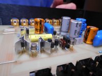
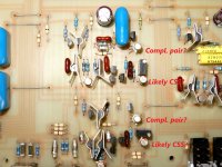
My supposition is that the dual can transistors are dual JFET complimentary pairs, and that is what part number U404 seems to be, even though my Atlas DCA Pro 75 is calling them voltage regulators. The two connected to the trimmers just read as two diode junctions, or as not detected at all. The part numbers U1732 and 6808 on those parts don't come up on a web search. The numbers on top appear to be Audire's numbers for their location in the circuit. Am I on the right track thinking those trimmers are for adjusting CSS voltage?
Due to the unknown part number I'm not sure which legs are D,S, or G, and my 'scope skills are very rudimentary, so I'm not even sure where to connect the probes but infer from your instruction that I would probe two legs, if I can determine D,S and G?
I really do appreciate your time, Chris - thank you.
My wife just said we should take a vacation to Canada and put this on your bench!
Cheers,
Greg
I appreciate your time trying to help an ignoramus. It must be a real challenge trying to convey things that must be rudimentary to you.
My supposition is that the dual can transistors are dual JFET complimentary pairs, and that is what part number U404 seems to be, even though my Atlas DCA Pro 75 is calling them voltage regulators. The two connected to the trimmers just read as two diode junctions, or as not detected at all. The part numbers U1732 and 6808 on those parts don't come up on a web search. The numbers on top appear to be Audire's numbers for their location in the circuit. Am I on the right track thinking those trimmers are for adjusting CSS voltage?
Due to the unknown part number I'm not sure which legs are D,S, or G, and my 'scope skills are very rudimentary, so I'm not even sure where to connect the probes but infer from your instruction that I would probe two legs, if I can determine D,S and G?
I really do appreciate your time, Chris - thank you.
My wife just said we should take a vacation to Canada and put this on your bench!
Cheers,
Greg
Attachments
Hi Greg,
That part is still available from 404 Not FoundDMOS Switches, JFET Amplifiers, BIFET Amplifiers, MOSFETS
This takes you to the product page where you can download their data sheet. This is a matched part of N-channel J-Fets
Other second source vendors will also have these, but Linear Systems makes really good parts. I also see a part labeled J204 I think. Another JFet type, maybe NLA these days.
Never forget that you are skilled in a different subject and I would be considered not very knowledgeable in that area!
-Chris
Note: What a messed up link! It works fine.
I am not sure why you would want to recommend an exchange of this precious part.
Remember what your wife says.
Did the OP check dc voltages between channels or not. It is possible with an ordinary multimeter.
The transistor tester will not always show an accurate result with certain parts (try Germanium).
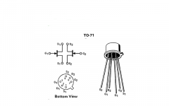
Drawing of a dual J-Fet attached. Most of the duals will adhere to this pin out.
Checked my Audire schematic collection, I don't have this one but sent an email to the distributor.
Remember what your wife says.
Did the OP check dc voltages between channels or not. It is possible with an ordinary multimeter.
The transistor tester will not always show an accurate result with certain parts (try Germanium).
Drawing of a dual J-Fet attached. Most of the duals will adhere to this pin out.
Checked my Audire schematic collection, I don't have this one but sent an email to the distributor.
Attachments
Thank you, AS_Audio, and Chris,
From reading many of anatech's posts going back years, I am sure he wasn't recommending automatic replacement, and definitely not substitution unless necessary. I've seen him warn others to keep things stock and diagnose the problems first, so I am taking that to heart, particularly with this rare preamp.
I did previously check DC voltages between boards at many locations (nice to have a good board to compare, and all test nodes are accessible at jumpers and elsewhere from the top of the boards), but was/am unsure what I should be seeing on which transistors. Now that I have confirmation of the dual JFETs (thanks, Chris) and the pinout you provided (thank you), I will take some readings from each board and compare. I'll also map voltages on one of my photos.
Am I on the right track about the trimmers being used for adjusting CSS voltage?
If I use my oscilloscope, am I attaching probes to Gate and Source?
Thank you for checking your schematics, but I'm puzzled by your comment about email to the distributor. Audire closed up even before Julius Siskinius died several years ago. I know that a guy in Southern California bought a bunch of his stock, but that's all I've heard.
Thank you both for your input.
Cheers,
Greg
Last edited:
I am pretty sure that the dual Fets are working unless
- somebody slipped with a probe or similar or
- damage happened due to overvoltage, thunderstorm etc if these are at the circuit inputs.
Do not touch the trimmers.
Scope tip can be used to check different points of the circuit, scope ground is connected with signal ground.
Scope can also be used for quick dc comparisons with input channel setting to "dc".
So if you own a scope let us compare screen pictures of both channels first with signal applied.
This should be a continuous signal, sine or square, no music.
I talked about the local Audire distributor. I made all the repairs, but never had a preamp in the workshop,
only power amps.
Hi AS_Audio,
I've actually been very cautious to avoid probing the transistors because of my lack of experience and awareness of static damage. I do use a static-safe pad and wrist grounding strap, but I've purposely not touched any of them with my scope yet.
The channel does work, but the DC offset trips the amp protection after about 30 seconds. Sound is a bit distorted, but equivalent volume to other channel.
Julius repaired this unit 2 or 3 times in the past 35 or so years. It looks like last repairs were to power supply section, and a couple of circuit tweaks but no parts replacements in the audio section. Last repair was in last few years of his life, and solder joints looked rough. My brother didn't report any voltage spikes or lightning prior to the preamp failing. I think it was gradual DC drift, but symptoms confounded by a bad volume pot.
Thank you for the tips re: scoping. I have a Rigol digital and a 465B, and a good sig-gen. I'll be out of town early next week, so will probably get to it Wednesday evening.
I have what you will find to be a very interesting story I'll pm you about - the huge, only one ever set of his full range panel speakers he made for my brother.
Cheers,
Greg
Last edited:
David,
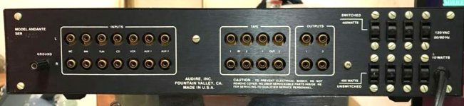
I'm not entirely sure, but I think it may have either preceded, or was concurrent with the Diffet line. On my other computer I have a copy of the brochure from my brother that shows the Andante, which was top of his line. I don't think many were sold, which may be part of why I can't find a schematic.
Cheers,
Greg
HI Greg,
You are correct, I was not recommending automatic replacement. The pin out was the main interest to help you to troubleshoot.
A 'scope ground is generally connected to AC mains ground directly inside the 'scope. It helps to keep that in mind in case connecting the probe ground lead changes the operation of the unit. What I do is connect the grounding lead to the chassis and probe with the probe - but I do not use the hook end. Take some heat shrink tubing that just fits over the metal part of the probe tip (take off the hook end) with some of the tip showing out the end. Use a heat gun on low, hair dryer or similar to shrink the tubing. Now you have a browsing tip that won't short on the grounded part of the probe tip. You will find this easier.
Set your 'scope to DC and touch the gate pins, one after the other noting the voltages. The two gates should be next to identical voltages if it is a diff pair and working properly. You cannot do this while running a signal through most times. Also, turn the volume on the amplifier if you are monitoring your output.
After doing your DC checks, then run a sine wave signal and compare levels with the working channel. Ideally, all this checking will be done when the preamp is in the fault condition. Otherwise your tests will probably show everything is all right.
-Chris
Thank you, Chris. I knew we were on the same page.
I'll follow your suggestion on the probes - thank you. I've used the tip before, but didn't think about shorting to the ground ring on the probe. Yikes.
The preamp always shows DC offset on the right channel, but never cuts out, so there is no actual transition from working to fault - that's happening at the amp. I'll probably not monitor output with an amp as I don't have a suitable low power test amp/speaker, but will use channel 2 on the scope.
Looks like I have great marching orders from both you and as_audio, so now I'm excited about getting back to this when I return from my work trip Wednesday.
Thank you, Gentlemen!
Greg
- Status
- This old topic is closed. If you want to reopen this topic, contact a moderator using the "Report Post" button.
- Home
- Source & Line
- Analog Line Level
- Need Your Assistance - Audire Andante