..and need more eyeballs to go over it.
I'm about to embark on a PCB layout, but would like a second opinion on
the circuit to see if I need more 'feature creep'.
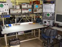
I have all this Tektronix 5000 series test gear and they all support
GPIB control to automate their behavior. The missing link is a
switchbox to change routing programmatic-ally to allow tests that need
external routing changes.
Some of those tests would be:
My Tek MI5010 is loaded with three 50M30 DIO cards and can drive up to
48 relays directly, so I don't have an issue if I need to add more
switching. Looks like I'm up to *just* 27 now 😉 A routing matrix for
doing an entire console at once is something I can do later/separate.
I'm just concerned about the single ins/outs right now.
So the question is... What did I forget?
Also, I tried looking at using a CPLD to data compress the states down
to 16-bit (thus just one 50M30), and even wrote the VHDL source for it.
The problem, or I guess my fear, is that I had to go with a Xilinx
XC9572-7-PC84. That's 84 pins!! Though I need 40 I/O lines, I barely touch
its capabilities... That, and a $230 programmer, too, but it is cheap @
$7.35 in singles
Digi-Key - 122-1444-ND (Manufacturer - XC9572-15PCG84C)
I'm about to embark on a PCB layout, but would like a second opinion on
the circuit to see if I need more 'feature creep'.
I have all this Tektronix 5000 series test gear and they all support
GPIB control to automate their behavior. The missing link is a
switchbox to change routing programmatic-ally to allow tests that need
external routing changes.
Some of those tests would be:
- input CMRR (both 50 ohm balanced and 600 ohm unbalanced)
- input impedance
- input shorting for testing noise floor
- line output impedance
- line output CMRR
- line output balancing tests to see that it unbalances properly
- microphone phantom power range
- amp output routing for different loads (8,4,2) including open-circuit
and an alternate speaker.
My Tek MI5010 is loaded with three 50M30 DIO cards and can drive up to
48 relays directly, so I don't have an issue if I need to add more
switching. Looks like I'm up to *just* 27 now 😉 A routing matrix for
doing an entire console at once is something I can do later/separate.
I'm just concerned about the single ins/outs right now.
So the question is... What did I forget?
Also, I tried looking at using a CPLD to data compress the states down
to 16-bit (thus just one 50M30), and even wrote the VHDL source for it.
The problem, or I guess my fear, is that I had to go with a Xilinx
XC9572-7-PC84. That's 84 pins!! Though I need 40 I/O lines, I barely touch
its capabilities... That, and a $230 programmer, too, but it is cheap @
$7.35 in singles
Digi-Key - 122-1444-ND (Manufacturer - XC9572-15PCG84C)
Attachments
yup. The Tektronix MI5010 with three 50M30 cards can directly power 48 relays and is controllable over GPIB. So a test suite summary example for measuring input CMRR would be something like this:
Input CMRR equals $a-$b all done by the computer and it should take 0.75 seconds or less.
Input impedance would be this off hand:
input impedance would then be $v2/(($v2-$v1)/1000ohms) and it should take 0.75 seconds or less to complete.
The question I have is... Have I missed any common tests in the switching unit that require routing changes? I think I have everything, but knowing myself.. as soon as I build it I'll realize something I forgot. I'd go over this with the other folks at the job, but none are qualified to help. That's why I'm here.
My test gear isn't that helpful to me if I don't ever follow through and automate it the way it was meant to be.. and frustration is the true mother of all invention because all the qualifying tests I have to do take forever and this isn't how things are supposed to be.
Code:
> switch bypass
< switch OK
> osc do sine;1000Hz;rms(1.228V)
< osc OK
> dist do measure db
< dist measure ready
> getdata dist -> $a
> switch input bal-CMRR
> dist do measure db
< dist measure ready
> getdata dist -> $b
Input CMRR equals $a-$b all done by the computer and it should take 0.75 seconds or less.
Input impedance would be this off hand:
Code:
> switch bypass;inputZ-V2
[INDENT]^- relay0 enabled on the input brd[/INDENT]
< switch OK
> osc do sine;1000Hz;rms(100mV)
< osc OK
> dist do measure volt
< dist measure ready
> getdata dist -> $v2
> switch inputZ-V1
[INDENT]^- relay0 and relay1 enabled on the input brd and relay5 enabled on the output brd monitoring across R1.[/INDENT]
> dist do measure volt
< dist measure ready
> getdata dist -> $v1
input impedance would then be $v2/(($v2-$v1)/1000ohms) and it should take 0.75 seconds or less to complete.
The question I have is... Have I missed any common tests in the switching unit that require routing changes? I think I have everything, but knowing myself.. as soon as I build it I'll realize something I forgot. I'd go over this with the other folks at the job, but none are qualified to help. That's why I'm here.
My test gear isn't that helpful to me if I don't ever follow through and automate it the way it was meant to be.. and frustration is the true mother of all invention because all the qualifying tests I have to do take forever and this isn't how things are supposed to be.
Attachments
more complete schems
more complete schematics of my switcher project idea. Not sure yet of the proper grounding scheme, but will follow AES54-2-2008 as best I can.. one input test does need a terminated pin1 at the DUT.
Usually my indicator of when a design is done, is when there is nothing more to take away. In this case, I guess I do need to churn out a unit and stop over-thinking it to discover missing features by using it <sigh>
I'll keep it modular (each schem will be PCB) so it'll be easy to mod.
The whole logic board will be the part that'll take the CPLD if I ever go that way. I'm up to 37 relays now. 4 more and I'll have to get a larger CPLD than that 84 pin one. bwaa haa haa.
Attachments
- Status
- Not open for further replies.