Hi folks
Need some experienced peoples advise here.
I have build a 4 way big speaker that i want to be able to use aslo Bi-wired ( so the possibility exist to use it with single amp or Bi-amp))
Woofer and mid-woofer have 150 W Continuous sine wave ( JBL 2235h and JBL E-145 ), but JBL 2405h tweeter and AGA compression driver with JBL 4322a horn (baby-butt) can take around max 40 watt.
And i want to give the woofer and mid-woofer the possibility of an external additional "stronger" amplifier.
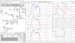
Problem is when i simulate to use only 1 amp, that its hard to get the impedance up at 260 hz ( 2,9 ohm) and also at 75 hz (3,1 ohm)
But no problem when using 2 amp/Bi-amp and separate low-midlow, and mid, tweeters xover.
Are they some magical trick" to get the impedance up a little without "stealing" dB from low-mid ( jbl e-145) with resistors ?
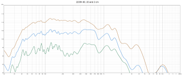
All files in zip, real mesaured spl and impedance in my boxes.
Also my Vituaxcad file with the simulation.
Help needed.
Best regards John
Need some experienced peoples advise here.
I have build a 4 way big speaker that i want to be able to use aslo Bi-wired ( so the possibility exist to use it with single amp or Bi-amp))
Woofer and mid-woofer have 150 W Continuous sine wave ( JBL 2235h and JBL E-145 ), but JBL 2405h tweeter and AGA compression driver with JBL 4322a horn (baby-butt) can take around max 40 watt.
And i want to give the woofer and mid-woofer the possibility of an external additional "stronger" amplifier.
Problem is when i simulate to use only 1 amp, that its hard to get the impedance up at 260 hz ( 2,9 ohm) and also at 75 hz (3,1 ohm)
But no problem when using 2 amp/Bi-amp and separate low-midlow, and mid, tweeters xover.
Are they some magical trick" to get the impedance up a little without "stealing" dB from low-mid ( jbl e-145) with resistors ?
All files in zip, real mesaured spl and impedance in my boxes.
Also my Vituaxcad file with the simulation.
Help needed.
Best regards John
Attachments
The solution to increasing the bass impedance is presented in many of the B&W service manuals. Use it.
FYI/FWIW, etc., Peter Noerbaek in Alpine, Calif. is apparently making a new batch of JBL 2235H.
That is real great news to hear GM!
Mine are brand new in boxes (dated 1994 september on cone inside), bought it from an 82 year old gentleman how had got severe tinnitus and give up hes 30 years old diy-project.
Same with the E-145 and 2405h.......All new in boxes with matching serialnumbers.
The solution to increasing the bass impedance is presented in many of the B&W service manuals. Use it.
Was try to find info on the B&W solution, but can´t find any service manuals on the internet without paying 20$.
Do you have some more information Lojzek ?

Woofer and lower mid impedance in your files newer fall lower than 7 ohms. It must be possible to optimize FR also in way that resulting impedance will not fall so low without adding resistors. One thing to try is to change order of lower mid filter stages, move 100uF and 7,5 mH to first stage place.
Other thing: Are you sure you low mid simulation is made correctly with correct impedance data? Filter seems to have so steep falls (about 20 db/octave) and high Q what are not close to standard 2nd order filter. Probaly you can tune filter components to lower Q and smaller falls what also increase impedances.
Other thing: Are you sure you low mid simulation is made correctly with correct impedance data? Filter seems to have so steep falls (about 20 db/octave) and high Q what are not close to standard 2nd order filter. Probaly you can tune filter components to lower Q and smaller falls what also increase impedances.
Last edited:
Woofer and lower mid impedance in your files newer fall lower than 7 ohms. It must be possible to optimize FR also in way that resulting impedance will not fall so low without adding resistors. One thing to try is to change order of lower mid filter stages, move 100uF and 7,5 mH to first stage place.
Other thing: Are you sure you low mid simulation is made correctly with correct impedance data? Filter seems to have so steep falls (about 20 db/octave) and high Q what are not close to standard 2nd order filter. Probaly you can tune filter components to lower Q and smaller falls what also increase impedances.
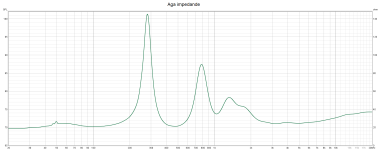
You are right, they never goes under ca 7 ohm "alone", but connected parallel with the low-mid is "another thing" ( se pic)
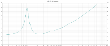
One of the reason low-mid behave " a little" strange", is that the 15" JBL E-145 only have 17,8 liter volym netto.
Q is 1,25
(Was trying to get ca 25 liter, but it was a complicated thing to build because i modified a old 3 way diy to a 4 way diy, and prioritized woofer volyme)
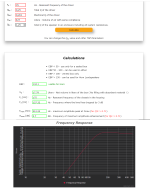
GM taught me how to calculate it with the impedance curve mesaured in the cabinette.
Low-mid´s impedancepeak is mesaured at 101 hz ( as mesaurement show) = 17, 8 liter volym netto.( VAS 427, QTS 0,25 )
The old AGA/Baltic cd is a 20 ohm driver, and JBL 2405h is 16 ohm
I will try change filter stages as you suggegest,
Thank you for your tip 👍
Attachments

Hi Jawen,
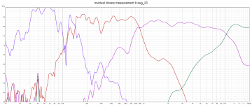
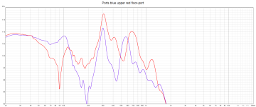
I think Kaameelis is pointing out the sharp corner transitions he has circled. you could try very gently playing with the Xover components to round them off, with only one value change on the L and C element no more than that or it will mess up what you have. Infact the upper transition at 800Hz doesnt look to bad to my eyes, which leaves the lower corner to try. You may have optimum for your ears already.
As to raising the impedance Lojzek's hint about having a resistor in the Capacitor shunt leg would seem like it will be worth modelling, maybe try 1 to 2 ohms in line with the 200 uF and 47 uF and gauge their effect maybe you will only need the resistor in only one driver chain to bring the impedance up enough ?
Keep us posted on how it looks.
Yes this I mean.
On LP filters increasing L increase Q, increasing C decrease Q (but less than L change) when all R remains the same.

On LP filters increasing L increase Q, increasing C decrease Q (but less than L change) when all R remains the same.
Hello
Couple of questions
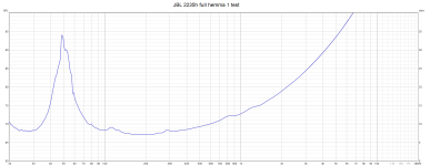
Is the 2235 in a reflex box?? The minimum imp shown is about 10 Ohms. It's an 8 ohm driver??
Is it sealed?? Why are you rolling off before 50Hz??
With the E-145 the sensitivity is about 5 dB higher than the 2235. You don't need to pad it down??
Rob 🙂
Couple of questions
Is the 2235 in a reflex box?? The minimum imp shown is about 10 Ohms. It's an 8 ohm driver??
Is it sealed?? Why are you rolling off before 50Hz??
With the E-145 the sensitivity is about 5 dB higher than the 2235. You don't need to pad it down??
Rob 🙂
Keep us posted on how it looks.
Hello Ray 🙂
Tested to put a resistor after the 200 uF cap and 47 uF cap, but "nothing happends" before i raise it to ca 3,9 ohm ( stealing many dB from low-mid)
And laborating with all sort of passive filter combinations, and maby are on my way to a "little better" impedance results.
Never give up 😉
Yes this I mean.
On LP filters increasing L increase Q, increasing C decrease Q (but less than L change) when all R remains the same.
Thanks
Will try to read a little, so i can "understand" how you mean.
Much very specific terms and calculations in diy, almost so it feels like the brain is growing between the crashes.
Is the 2235 in a reflex box?? The minimum imp shown is about 10 Ohms. It's an 8 ohm driver??
Is it sealed?? Why are you rolling off before 50Hz??
With the E-145 the sensitivity is about 5 dB higher than the 2235. You don't need to pad it down??
Hi Rob
The 2235h is in ca 100 liter reflex box with 2 ports ( 100 mm wide, 43 cm long is what i recall )
The impedance mesaurement is from mounted in box ( both the 2235h and E145)
You ask me "Why are you rolling off before 50Hz??"
And im not a pro but think its because my "bad" low frequency measurement/FRD file in the simulations.
So complicated to mesaure under 2-300 hz, and nearfield mesaurements and port mesaurements are much higher in "level" than the rest
But had made a conclusion over time to "not give the woofer/sub" to much attention in simulations regarding to curves or dB.
Because if you know that the drivers circumstances is good i.e litervolyme, cabinette, ports, driver and amp, you can´t do much more then to placement of the speaker and choise of room.
Attachments


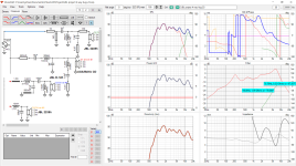
With rearrainging filter elements
Thanks kaameelis
I will check out it more deep, but impedance look good!
One thing i notice instantly is the "rippel´s" from 8-900 to 2,3K, and that you put a 20mH coil instead of 10mH at the woofer.
Maby i can sell my other kindey 😉
And have to ask, is 39 uF sufficiently for a JBL 2235h working up to 150-175 hz ?
Okey i´m back ( with a little more grey hair )
Seems "inpossible" to get "perfect" output all the way ( 150-850 hz) from low-mid/Jbl E145 in only 17,8 liter netto to work in. ( as i have )
The problem are mostly below 300 hz where output is inhibited about -5 dB.
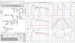
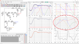
Maby i try this solution in the picture from my Vituaxcad, impedance are quite good exept at 6500 hz where it dropps to 3,1 ohm, but belive that will work.
Also almost 25ohm short peaks at 42 hz and 1250 hz ( in the simulation)
And the "filter-panel" in the six-pack i Vituaxcad looks unusual to say the least, but it doesn't bother me much
If i let the woofer/Jbl 2235h work a little higher up and leave more output up to ca 200 hz, it blend in quite fine with the low-mid.
I also have thoughts on whether it would be better "response" from the E145/low-mid if i made it vented with a smal port.
What do you think guy´s ?
Seems "inpossible" to get "perfect" output all the way ( 150-850 hz) from low-mid/Jbl E145 in only 17,8 liter netto to work in. ( as i have )
The problem are mostly below 300 hz where output is inhibited about -5 dB.
Maby i try this solution in the picture from my Vituaxcad, impedance are quite good exept at 6500 hz where it dropps to 3,1 ohm, but belive that will work.
Also almost 25ohm short peaks at 42 hz and 1250 hz ( in the simulation)
And the "filter-panel" in the six-pack i Vituaxcad looks unusual to say the least, but it doesn't bother me much
If i let the woofer/Jbl 2235h work a little higher up and leave more output up to ca 200 hz, it blend in quite fine with the low-mid.
I also have thoughts on whether it would be better "response" from the E145/low-mid if i made it vented with a smal port.
What do you think guy´s ?
Attachments
- Home
- Loudspeakers
- Multi-Way
- Need to add 1 more ohm in my passive 4 way xover