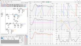
One question: why D1 and D3 filters are overlaped in wide range as also D4 and D3 filters? Generally this is not needed.
I really don´t know kaameelis !
All i can think of is that both D1 and D3 don´t have any high-pass filter, so the "filter-panel" in Vituacad don´t "cut" it downwards in that panel?
D4 have low-pass, but D3 dosen´t have high-pass filter ( so i gets everything that the components don´t "take care of" )
Do you think otherwise?
I think Kaameelis is referring to the shapes of each speaker response. not being very symmetrical compared to some design norms.
However, the data from Vituixcad shows an overall sensible frequency response, and at the same time you were chasing down an impedance question, which is now better.
This demonstrates that there are many solutions to this problem. To get where you are today you have obviously tried many iterations.
Going back to the idea of symmetry could be a useful guide for future modifications, but it will take you more time and effort.
As a simple observation as designs move away from two ways into three ways and beyond the roll on and roll off tend to start matching the slope of the preceding driver even if they are achieved by the application of differing electrical filter components. Please look toward the bottom of this page for filter slope drawings that show this in a way far better than I can explain. Also you need drivers that have plenty or enough frequency overlap to allow you to shape the filter response at the required frequency.
https://www.linkwitzlab.com/crossovers.htm
There is years of knowledge and wisdom contained in that single page, and no I don't understand all of it. I need to try harder.
I obviously don't know how your current design sounds in your room, are you happy with the results you are getting now and do they match the simulation. How much more work do you want to put into this?
Every change or step we make with a design we learn more, not many people get to design a four way, including myself.
Take care and have fun.
In first version D3 had HP filter, why you removed it (actually partly only)? D1 has also in latest version HP filter, but it is tuned too low, also D3 HP is too low.I really don´t know kaameelis !
All i can think of is that both D1 and D3 don´t have any high-pass filter, so the "filter-panel" in Vituacad don´t "cut" it downwards in that panel?
D4 have low-pass, but D3 dosen´t have high-pass filter ( so i gets everything that the components don´t "take care of" )
Do you think otherwise?
This filters overlapping can also cause too low impedance values in overlapping regions.
think Kaameelis is referring to the shapes of each speaker response. not being very symmetrical compared to some design norms.
Hallo Ray, and thanks for your input 🙂
Yes i´ve workt many many hours on this diy speakers/xovers, and around 19 may i was minutes from "a completly finished perfect xover", but i had work so much many day in a row, so my bad back and neck was hurting like hell.
So i decided to give my "body" a few days rest, but 2 days later my daughter & her friend run in to my xover ( laying on the floor, and 60+ other loose xover-components)) when they played, so every solderpoint on the " finished xover " come loose and was mixed with all other 60+ components !
That filter was supergood and build in only 1 week without notchfilter etc, and even without having impedance curve for the AGA driver or real made impedance curves in the actual boxes for all the drivers.
Work´t on 3-4 different xover at the time and made many notes ( I thought), but REW craches from time to time, and almost no mesaurement was left from that timeperiod.....And my head was "full" and had a little of "everything", but even now 3 months later and with all correct curves for the drivers, i still can´t come back to the same "point".
It´s sad but im learning "by misstakes" the hard way. ( will never work on 3-4 xover at the same time again, and make more evident notes)
The speaker sound great Ray, but need to decide the "exact" xover, so i finaly can put it in and finish the speakers back-plate and smal other things.
I will look at the link 👍
And i know my filter-curves are not symmetrical compared to design norms, and i know how they should look like
But the low-mids smal box, and the AGA complicated spl and impedance curve, made me to try it all.
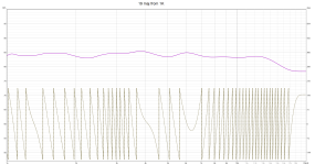
This was my mesaurements from maj........In a png file, but real mesaurements and notes are gone from one of REW many craches
Take care Ray !
Attachments

In first version D3 had HP filter, why you removed it (actually partly only)? D1 has also in latest version HP filter, but it is tuned too low, also D3 HP is too low.
Yes kaameelis, i try out all possibilitys.
The response/spl-curve for the E145/low-mid never gets great however high values I go up to...and and whatever I do.
So just try with "this" combination-xover, and ask you people what you think of it.
The low-mid have to smal box i think and yes D3 had a HP filter in the last filter, and i just "brainstorming" with this solution.
I remove the big coil because i couldn't get a nice spl-curve even with large coils and caps......and also impedance "problem"
The D1 is problematic and the "new" notchfilter that needed to get flatter curve ( take away the "ending") of the HP filters function.
Have you some solutions for E145 and AGA drivers ?.....feel im stuck in my brain.
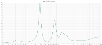
This is tha AGA spl curve in the horn and the impedance curve i have to work with,.
and also a minimal xover with 10 uF, 5,6 ohm to ground, 0,3 mH and 1,8 uF to ground.
My head is spinning and i appreciates your inputs kaameelis 👍
Attachments

What way I design filters (this is not mandatory only one possible way) is:
Make standard filters as described in https://www.linkwitzlab.com/crossovers.htm for all drivers on decided frequencies.
Then tune C, L, R values to get smooth SPL graph and impedance, do not forget to change drivers polarity where needed, but do not change filter frequencies too much, concentrate on filters line form and phase changes (phase changes can help a lot to fit drivers SPL lines). Maybe series R are needed for some C and zobel networks.
Vituxcad have also filter optimization function, it is not easy to use, reasonable is not to let it optimize more than 2 elements at same time, but it can speed up optimization if you are familiar with this software.
If with some filter parts/drivers optimize is not possible to get needed SPL line, then change filter topology, use higher order filters and/or add series or parallel resonant networks.
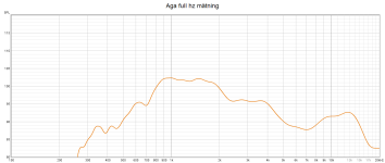
Your Aga10uf5 .6 graph looks well listenable to me.
Was that before the crossover was acceptable dentally adjusted?
Was that before the crossover was acceptable dentally adjusted?
Your Aga10uf5 .6 graph looks well listenable to me.
Yea Ray, it´s simple and cheep and sounds good 👍 ( But maby can sound better ???, nobody knows before trying)
It was a test after "the accident", when i was frustrated, don´t know if the xover/ filter topology is bad in some way, but maby you know.
Make standard filters as described in https://www.linkwitzlab.com/crossovers.htm for all drivers on decided frequencies.
Then tune C, L, R values to get smooth SPL graph and impedance, do not forget to change drivers polarity where needed, but do not change filter frequencies too much, concentrate on filters line form and phase changes (phase changes can help a lot to fit drivers SPL lines). Maybe series R are needed for some C and zobel networks.
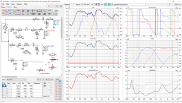
Hi again kaameelis
I took you word and have really tried to follow your and Ray´s advice, and have stuggle with a almost impossible assignment.
Really can´t get nice "Filter-frequency-curves" on all drivers together, and the same time have real good SPL-response and keep me over 3,8 ohm.
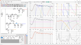
This is the best i can do, and i have made 3 different xovers to show you guy´s, and ask you if one of them is "more right"
Been a nightmare to raise impedance so i can use the speaker both with one amp or Bi-amp it with stronger amp for the woofer and low-mid.
Any questions or information on the xovers i have simulated is much appreciated.
Best regars John
Attachments

Hi Jawen,
Thanks a lot, that's a real tricky question as we haven't heard them and we may not like the sound you are after.
The second and the third iteration look reasonable enough. Not sure why you have so much going on around 700 - 1100Hz? Maybe try the mike in a different position to see if that changes ?
A question if you ignore the overall frequency response shape and make the drivers behave without the peaks at the end or beginning of the passband what does your response then look like. At the same time what happens if you drop your resolution to a 6th or a third of an octave? I sometime do this to help me understand if i have a major issue or I have become fixated on one bump?
Good luck. 🙂

This is really complex challenge.
Specially because drivers not easy FR.
To visualize the complexity I made naked project without filters, naked drivers FR-s.
From this can be seen what frequencies is reasonable to select for filters.
Actually I need also to ask: how you measured drivers FR and how reliable they are?

Specially because drivers not easy FR.
To visualize the complexity I made naked project without filters, naked drivers FR-s.
From this can be seen what frequencies is reasonable to select for filters.
Actually I need also to ask: how you measured drivers FR and how reliable they are?
and we may not like the sound you are after.
I think we like "about the same" sound, clear "sparkling" hi-mid ( but not to much), and good punch from low-mid, with deep solid "invisseble" bass.
Vocal, Piano and aucustic gitarr must sound great.
Is this what you mean Ray?
A better "filter-curve" ? ( but shitty spl-curve)
Attachments
This is really complex challenge.
Specially because drivers not easy FR.
To visualize the complexity I made naked project without filters, naked drivers FR-s.
From this can be seen what frequencies is reasonable to select for filters.
Actually I need also to ask: how you measured drivers FR and how reliable they are?
Yes, complex it is......And a "hate and love" challenge.
Yes, the curves look like sh-t kaameelis, and if i havent heard how superfantastic they sounded ( before my first xover was destroy), i not have tought that this combo was something to work with in my DIY.
Before i begain with this diy, my goal was 2235h up to about 150 hz, and E145 up to about 850-900 hz, Aga up to 7K ( but change it to ca 10K because of the 2405h)...Nothing is a fixed decision, and I follow the compromises I have to make in the project to get the best of it.
Any thoughts on the xover-points ? ( 150/850/10K)
The low-mid have 2 problem i think.
First its mounted 48,5 cm (center cone) from the floor, and a 15 inch have big "polar/spreads the sound widely.
Hard to do good mesaurements because the bounce in the floor, and have tried with pillows and stuff its a problem anyway.
The speaker also weight 150 kilo each, but i use a "pully" to get one of them outside the 13 of May.
Sadly i haven´t good mesaurement skills (yet), and my garden-floor also made some inpact offcourse, and of top at that REW crasch at the end and it was gettig dark and rainy....So i had to take the speaker inside again over night
And when REW crasches and you re-start it again, (REW say that the shutdown was faulty, and ask if you want to load the mesaurement again, but if its more then 30 "all goes to hell" ( and i had 230 ) so that was it!
So had only 1 mesaurement left from E145 and AGA driver, and more from the 2405h and the 2235h.
And 2 times i have try make new mesaurements inside for the E145 and AGA, but still not easy because of the 150 kilo.
And maby the E145 will work "better" if i ported the smal 17,8 liter netto cabinette?....( maby breathing problems?)
Is thinking of i can tilt the speaker backwards so less floor-bounce in the mesaurements ?
And the woofer/2235h mesaurements isen´t so "important", because i allready know they working really well.
Regards John
It is also possible to get decent measurements of drivers in room. You need to place speaker from any wall as far as possible, place mic about 1 m from speaker and make gated (about 3 ms gate) measurements of frequencies higher than about 300-400 Hz, nearfield measurements of frequencies lower than 300-400 Hz and combine measurements. This way is possible to get individual drivers response good enough to make initial version of filters and after you can tune filters by measurements from listening positions.
For best selection of filter ferquencies are needed also drivers in speaker polar plots and THD measurements, but it is possibe to get reasonable results without this measurements.
For best selection of filter ferquencies are needed also drivers in speaker polar plots and THD measurements, but it is possibe to get reasonable results without this measurements.
- Home
- Loudspeakers
- Multi-Way
- Need to add 1 more ohm in my passive 4 way xover