ok, so a few days ago i found a lm12clk dual mono amp kit here in japan, it does not show what the input voltages are exactly, but from the horribly printed power supply schematic that it came with it has two +10-25v, two -10-25v and an E voltage input, the power supply schematic that it came with is very basic, it has a transformer, diode bridge and 2 4700-10000uf capacitors, it does not show the capacitor polarity.
i bought a sinko transformer 3amp max with inputs for 90, 100, and 110 volts and outputs for 0, 0, 17.5, 28, and 35 volts, i got a small 4amp diode bridge that should be more then enough, and two nippon chemi-con 10000uf 35v capacitors.
the first try i used the 28volt outputs on the capacitor to the diode bridge and got 24 volts dc out of the diode bridge, then i hooked up the two capacitors with the negative of one wired to the positive of the other and the voltage across the open positive and negative ends of the capacitors, i didnt check the voltage and i hooked them up to the first amp along with the 0 out from the transformer as it said in the schematic, plugged it in and POP!! two small transistors exploded, so i went back to figure out where i went wrong.
then i tested wiring straight from the diode bridge on the good amp half to see if the kit actually worked on those voltages (not the best idea i know, but it was a cheap kit and i didnt really care much) and it powered up fine, but it only made a bunch of noise on the speaker since it was un filtered power.
then i tried using a 25volt power supply that i have (it doesnt have the 0v out) and i got some staticy sound! but the pre-amp section didnt power up due to the missing 0volt input. but that showed me that there is some hope for this little kit.
then i tried getting voltages from a few different setups on the capacitors, first i wired the capacitors the same as the first test except this time i put the 0 out from the capacitor on the wire that was tieing the two capacitors together and the outputs were about 70 volts dc! and each capacitor had almost 40 volts on it! i know that would blow up the amp for sure! then i tried with only one capacitor and the 25volt out from the diode bridge turned into 35 volts when connected to the capacitor.
so what am i doing wrong? how do i get the voltages to what i need?
Attachments
I honestly can't see anything wrong with the schematics drawing nor the circuit. This is a very common rectifier circuit.
But...
- what are the AC secondary voltage? did you measure and sure they are as expected/written?
- then what is the dc rail voltage?
But...
- what are the AC secondary voltage? did you measure and sure they are as expected/written?
- then what is the dc rail voltage?
hmm, well i cant get to it right now (at work) but i'm pretty sure that the secondary voltages on the transformer were arround 24vac reading across 28 to 28 volt terminals, but i know that after i connected those terminals to the diode bridge i was reading 24vdc, but then when it was connected to the capacitors, those same + and - leads from the diode bridge jumped up to arround 70vdc from the center tap to each was over half (arround 40vdc) which was not good especially since the capacitors are only rated at 35 volts (i then quickly shorted the caps to hopefuly not kill them).
First you need to be 'sure' rather than "pretty sure" about voltages or you will come to grief!
If you have 28 VAC on the output of the transformer, then you will get around 39-40 VDC after the rectifier bridge. If you have 24 VAC on the output of the transformer, you should be measuring around 33-34 VDC after the rectifier.
So from what you tell us, the traffo is putting out 28 VAC, not 24 VAC!
Hi,
don't test a PSU using an amplifier.
Use a voltmeter and dummy load (power resistor of suitable value).
don't test a PSU using an amplifier.
Use a voltmeter and dummy load (power resistor of suitable value).
kyleaudio said:... then when it was connected to the capacitors, those same + and - leads from the diode bridge jumped up to arround 70vdc from the center tap to each was over half (arround 40vdc) ...
the rectifier only inverts the negative side of the AC voltage, which means that there is a massive ripple - and your multimeter measures an average voltage (multimeter set to DC, 100hz\120hz ripple frequency)
the caps charge to the peak voltage (with no load) so 28VAC *1.414 = about 40v. if you test the supply with a load, the voltage will be lower - and if you check with a scope you will see the more you load the psu the worse the ripple gets
ok, two more questions (sorry for the noobishness)
1. if i am reading 24vdc on the output of the rectifier, then hook up the capacitors with a proper load resistor then i should get 24vdc across + and - correct? for now i will be using a 75watt 3.01 ohm dale resistor (the only high wattage load resistor i have on hand right now).
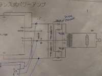
2. it is very hard to tell in the schematic since all of the connection point dots are very faint, should i have the 0v out from the transformer connected to the wire connecting the capacitors as it is in the picture above or should it be run directly to the amp? my guess would be to connect it so that it gets filtered.
again, sorry for the noob questions.
1. if i am reading 24vdc on the output of the rectifier, then hook up the capacitors with a proper load resistor then i should get 24vdc across + and - correct? for now i will be using a 75watt 3.01 ohm dale resistor (the only high wattage load resistor i have on hand right now).
2. it is very hard to tell in the schematic since all of the connection point dots are very faint, should i have the 0v out from the transformer connected to the wire connecting the capacitors as it is in the picture above or should it be run directly to the amp? my guess would be to connect it so that it gets filtered.
again, sorry for the noob questions.
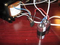
ok, well i used the 17.5 volt leads on the transformer (for some reason they were reading just below 10vac) and wired it with the center tap connected to the connecting wire on the capacitors, tested it with a dummy load first and connected to the amp across +vdc and -vdc i get about 47vdc, and the center tap to either positive or negative is about 24vdc and the amp is working just fine, thank you guys for the help and again sorry about the noobie questions. and here is a picture of the rough wiring, next step is to clean it up and get an enclosure.
Attachments
Hi,
don't connect that 3r0 resistor across 24V.
It will try to draw 8A.
the transformer is not rated for that,
the diode bridge cannot recharge the caps fast enough to support that load and the ripple in the caps will overheat them.
Start with measuring the DC voltage on each half of the dual polarity supply. Check that the voltage across each cap is correct and of the correct polarity.
Add a 1k0 resistor and measure the change in voltage across the caps.
Change to 100r resistor and again check the voltage.
Now try a high load current using 30r resistor. Preferably two of them so that each half of the PSU is loaded. Power rating required>=24*24/30=19.2W (minimum ~=25W on a heat sink).
- Status
- Not open for further replies.
- Home
- Amplifiers
- Chip Amps
- need some psu help