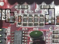
I’m hoping someone can chime in as I’ve posted elsewhere with no reply. I am working on the same amp, replacing PS mosfets, should I also replace the 100ohm with 47ohm gate resistors? This is the 06ZX750.1 early model. I am also getting some wonky reading randomly on the gate resistors for both output sides, some 104 are reading between 33k-50k ohm and one is reading 100k ohm, the 100 read find except one, that has no value. Would love a schematic on this amp, and just to confirm the gate resistors marked 104 and 100 are both size 1206 and I think they are 1/8 w? Sound right? Any help would be awesome, ty!
No value? Open?
The 100k that read 33k are reading that because there are 3, essentially in parallel. The same for the ones reading 50k (2 in parallel).
All 1206 are essentially going to be the same wattage. Order 1206 and you'll be OK.
I don't have the diagram you want but if you are unfamiliar with this type of amp, the attached diagram will show you what you're dealing with.
Attachments
Amazing, ty bro, really helps a lot! And as far as wattage I ask cuz I’m seeing 1/4 watt, 1/8 watt, etc, what wattage should I go with?. I’m going to look at the diagram you posted. As far as the 1 100 not reading anything that’s most prolly dead right? Ty again man, fr 🙂
Post working links to the 1206 resistors that are rated for 1/8 and 1/4w.
If the resistor is open, it's defective. If it's a gate resistor, it's also likely that the FET connected to it is blown.
If the resistor is open, it's defective. If it's a gate resistor, it's also likely that the FET connected to it is blown.
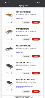
Ok, I’ll check the output mosfet attached to the 100 resistor with no reading, thought I did and it was fine but I’ll double check, the 104 attached to it is reading full value of 100k. And here’s a pic of the digikey SMD 1206 10ohm resistors with diff wattages, maybe I’m not searching right? Searched for “SMD 1206 10 ohm resistor”
Attachments
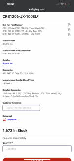
Also in digikey search I just noticed you can search by wattage also, just brought up all the smd 1206 10ohm resistors with .5 wattage. Would this be suitable for specs I want? Everything looks kosher, to a layman anyway 😅 the diagram you posted is showing same output fets and gate resistor ohmage as the amp I’m fixing so I’m assuming the .5 wattage is also what I want.
Attachments
The power rating is based on the amount of heat that they can withstand and the physical size, which determines the surface area. Virtually all are made of the same basic materials so they can withstand the same maximum temperatures. The same physical size means that they can all dissipate the same amount of heat.
For the way they're being used, a 1206 of any rating will survive.
Was the FET with the open gate resistor shorted?
For the way they're being used, a 1206 of any rating will survive.
Was the FET with the open gate resistor shorted?
Ahh ok, ty. And I just tested and the mosfet is good, and the resistor @ R210 SMD100 is actually reading 150k ohm, thought it was dead cuz I had it set on lower ohm setting but decided to go thru the settings just to see and ya, 150k >.>
If the resistor is not 10 ohms, ±5%, it's defective.
Are you sure that Q132 isn't shorted from the gate to either other terminal?
Are you sure that Q132 isn't shorted from the gate to either other terminal?
I don’t know how to exactly test for that, I’m using diode/beep mode on dmm, going from legs of mosfet Q132 like this > 1&3, 1&2, 2&3 and no beeps/shorts on any mosfets on either side of output. There a beep when testing one side of 100 to leg 1 and from one side of 104 to leg 3, they all do that tho, assuming that’s how they are connected trace wise. I apologize for my newbness bro, learning as I go. When you say “shorted from the gate of either other terminal” what do you mean exactly?
Last edited:
What's the resistance between the gate leg of R132 and the gate legs of Q133 and Q131?
Set your meter to the 200 ohm range if it's not autoranging.
Set your meter to the 200 ohm range if it's not autoranging.
If the resistor doesn't have bad solder connections, you will need to replace it.
I'd recommend replacing all of the 10 ohm gate resistors for the 3 parallel 9640 FETs.
I'd recommend replacing all of the 10 ohm gate resistors for the 3 parallel 9640 FETs.
ok ya, the other side of the output with the 9640 mosfets are measuring 33k at the 104 resistor, 640 mosfet 104 gates read 50k, assuming this wonky side is supposed to read the same, the bad resistor at R210 is effecting both adjacent readings, just learned that lol. Im going to order the 10 ohm 1206 .5 watt resistor I posted a pic of. Really appreciate your help man, this is a lot of fun learning everything 🙂
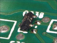
So I’m going through the board and noticed a hole in Q103, Q100 looks to be same type (markings ASG DH?) regardless what leg I touch to what leg with my DMM in beep mode it shouldn’t go off correct? I was watching a repair video of same exact amp with same problem and Q05 & Q11 had a hole in them on his amp, so I tested mine and Q05 didn’t set off my diode tester but Q11 did when I touched both the legs on same side, assuming it’s bad? Q103 (one with hole) beeped when I touched the single leg on on side to bottom leg of double legged side, Q100 did not beep at all regardless what leg I touched to what leg) going through board for other physically damaged looking parts. What type of component are each of these? They look the same just diff markings and diff sizes, ty for any additional help 🙂
Attachments

Great info at the beginning of this thread, going to check links, etc and use that info as well, this is becoming THE goto page for repairing zx 750.1 Power Supply side lol 🙂
Malak debating changing the good gate resistors on the PS side from 100 to 47 ohm ...must be a reason they changed it, recommended while in at it anyway? Going to start probing everything for shorts near the bad ones I found in pics above. Ty for all your help Perry 🦾
Malak debating changing the good gate resistors on the PS side from 100 to 47 ohm ...must be a reason they changed it, recommended while in at it anyway? Going to start probing everything for shorts near the bad ones I found in pics above. Ty for all your help Perry 🦾
The ASG transistors are KTA1504s. Lift the transistors (as shown below) to test. Remember to test 1-2, 1-3, 2-3 then reverse the probe orientation and re-check.
https://www.s-manuals.com/smd
The previous information was generic. When it comes to more specific information, PapaZBill will have more definitive answers.
https://www.s-manuals.com/smd
The previous information was generic. When it comes to more specific information, PapaZBill will have more definitive answers.
Attachments
Last edited:
Ty, didn’t mean to flood you with questions just really getting into it and it seemed you know much more then the avg layman 😅
- Home
- General Interest
- Car Audio
- Need schematic for kicker zx750.1