Can someone point me to a good voltage regulator circuit for a high (-70V) supply? The transformer rating is: 50V, 0.1A out @ 120V, 60Hz in. I don't need a dual polarity supply, just the one single supply.
So far all of the voltage regulator IC circuits I've found top out well short of the voltage I'm using; using separate components isn't a problem.
Thanks.
EBS
So far all of the voltage regulator IC circuits I've found top out well short of the voltage I'm using; using separate components isn't a problem.
Thanks.
EBS
Almost any voltage regulator needs more input voltage than output voltage.
Depending on the load your 50V transformer may not even supply 70V DC
let alone the 72Vdc or higher you will need. Do the math 50VAC X 1.41
= 70.5 VDC - ~2V ( droped across the bridge rectifier) = 68,5 VDC so you
don't even have 70VDC let alone any extra for the regulator to play with.
But at a verry light load that transformer will probably be closer to 60VAC
so you may want to build a DC supply and test it under your expected load
to see if you do have some voltage to work with.
Woody:
Thanks for the reply.
I can tolerate some drop in the actual working voltage. If I wind up with something in the 60 - 65V range it will be fine. If I have to use a bigger transformer to get there that's fine too. It's the regulator circuit that's got me stumped at the moment.
EBS
Thanks for the reply.
I can tolerate some drop in the actual working voltage. If I wind up with something in the 60 - 65V range it will be fine. If I have to use a bigger transformer to get there that's fine too. It's the regulator circuit that's got me stumped at the moment.
EBS
You can use a voltage doubler to deal with the voltage drop across the regulator. How large a current does the load circuit draw?
Use the TL783 high voltage regulator and reverse the outpots
as is discused in this link.
Re: Voltage regulator
as is discused in this link.
Re: Voltage regulator
I can tolerate some drop in the actual working voltage.
Don't understand this. If you can tolerate that the regulator does not regulate, why do you then need a regulator?
Have a look at the old-age but still interesting LM317, it's nothing that has not been done with it... For example: www.national.com/ms/LB/LB-47.pdf
Don't understand this. If you can tolerate that the regulator does not regulate, why do you then need a regulator?
Have a look at the old-age but still interesting LM317, it's nothing that has not been done with it... For example: www.national.com/ms/LB/LB-47.pdf
Sorry.
I can accept some voltage less than -70V due to the requirements of the regulator circuit. Say -65Volts as long as the -65Volts is regulated.
Thanks.
EBS
Why not go for something discrete?
It is barely more complex than an integrated regulator, but more flexible and more robust.
Here is an example: the performances are comparable to an integrated regulator, and as a bonus, it is low drop-out.
It is barely more complex than an integrated regulator, but more flexible and more robust.
Here is an example: the performances are comparable to an integrated regulator, and as a bonus, it is low drop-out.
Attachments
Nice circuit, has better PSRR than a LM317. To my opinion the drawback is missing current limit and thermal protection. How are line and load transient response, temperature stability?
Current limit could be added relatively simply, overtemperature protection is another story.Nice circuit, has better PSRR than a LM317. To my opinion the drawback is missing current limit and thermal protection. How are line and load transient response, temperature stability?
But if you insist on having all the bells and whistles of a monolithic regulator, the best option is probably to use one.
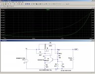
Here are some additional performance curves:
-Temperature sweep 0-->75°C
-Line transient 25V pulse on top of 70V input
-Load transient 100ohm added to initial 200ohm.
Notes:
The tempco is caused by the zener and the transistor's Vbe. If it is a problem, it could be compensated by stacking ~4Vbe in series with R4.
The sharp spikes at the edges of the transients are caused by the internal capacitances of the MOS ballast.
Adding a decoupling capacitor at the output could reduce them substantially.
Attachments
But if you insist on having all the bells and whistles of a monolithic regulator, the best option is probably to use one.
Don't want to insist, just want to mention that both ways to go have its pros and cons.
Here is the current-limited version.
It also includes a compensation resistor R8 bringing the output resistance below 1milliohm.
At this voltage level, a fold-back limitation is probably a good idea: next pic, only one more resistor R9 is required.
PS
At this stage, the circuit is probably much more resilient than an integrated one, even without overtemp protection
PPS
With the addition of R6, the circuit doesn't qualify anymore as a LDO: it needs more than 1 volt delta to regulate properly.
You cannot have it both ways.
Attachments
Last edited:
Hi there ! I found this Elvee's solution so much interesting. Long time has passed and still interesting ! Unfortunately my inexperience with this kind of designs make me ask you if you could give me some advice. I will very much appreciate it because I need to apply this design in an amplifier VAS stage.
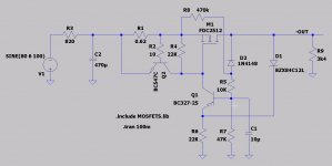
I tried to simulate the same circuit with LTspice but I am doing something wrong. The PSRR I get is about -50db and the voltage drop is high. I implemented a positive version of the same circuit. It works exactly as the negative version with the same problem.
The input is a 2 to 12 VAC sine wave mounted over a 80 VCC voltage to simulate ripple in some way. The output is very good about 63 VCC and about -43 to -50db ripple.
I tried with a couple of MOSFETs but the result is more or less the same. I had problems with the 1Meg resistor, R8 in my negative drawing version, and had to reduce it to 470K to make it work.
I am attaching both LTspice simulation .ASC file and a MOSFET library.
Could you please tell me what the error is ? I was trying to get something about -100 to -120 db PSRR with a drop of no more than 10 V.
Best regards !
Attachments
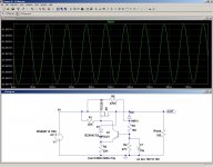
Your circuit is incapable of regulating, because the input voltage is (slightly) lower than the theoretical regulated output.
Of course it is a LDO, but asking it to compensate for an insufficient input is perhaps a bit too much? (unless it is of a switching variety, of course).
The problem is caused by the drop in R3: if you want to keep it, you need a slightly higher AC input, 82V is sufficient:
Of course it is a LDO, but asking it to compensate for an insufficient input is perhaps a bit too much? (unless it is of a switching variety, of course).
The problem is caused by the drop in R3: if you want to keep it, you need a slightly higher AC input, 82V is sufficient:
Attachments
Your circuit is incapable of regulating, because the input voltage is (slightly) lower than the theoretical regulated output.
Of course it is a LDO, but asking it to compensate for an insufficient input is perhaps a bit too much? (unless it is of a switching variety, of course).
The problem is caused by the drop in R3: if you want to keep it, you need a slightly higher AC input, 82V is sufficient:
Elvee thank you for your reply. I didn't said that the circuit does not regulate. The circuit regulates nicely, as you say, from around 80 VCC input and delivers around 63V output. I added this brutal 12VAC ripple over the input voltage and tested not only 80VCC input but also 120 VCC with same results.
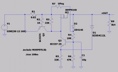
What I am looking for, is the positive version of the circuit, and I tried (in my ignorance) to figure out a mirrored version, and I think it is working. Here is where I need your blessing and opinions. Is the positive version good as shown ?
The second issue for both versions concerns to PSRR because I can't get better than -50dB rejection, while I see that your simultaion run gets -70dB or better. Somebody said that is better than an LM317 chip, but to my knowledge this regulator chip obtains -120dB rejection. Why does my simulation doesn't show such good figures ? Could you share your LTspice .ASC file so I can study it ? Some wrong simulation parameter on my version?
I used different transistors because I need the MOSFET to be TO-220 or similar. What is the main feature for these MOSFETs ?
Finally, how can I get less voltage drop ? Which components should I adjust or change ? I need 70 to 80 VCC output with -80 to -100 dB PSRR and not more than 50 mA output. I have +/- 120 VCC available for both regulators.
I would like to hear your advice. Many attachments of my simulations if you may like to check them. As I said before it is a very nice discrete circuit.
Thank you in advance.
Roberto
Attachments
-
HV_Reg_Negative.asc2.7 KB · Views: 165
-
Negative output for 120VCC+12VAC AC analysis.pdf133.9 KB · Views: 167
-
Negative output 120VCC+12VAC waveforms.pdf139.3 KB · Views: 167
-
Positive output regulator simulation schematic.pdf52 KB · Views: 179
-
Positive output for 120VCC+12VAC input waveforms.pdf110.5 KB · Views: 156
-
Positive output for 80VCC+12VAC input waveforms.pdf123.5 KB · Views: 129
-
Negative output regulator simulation schematic.pdf51.9 KB · Views: 209
-
Negative output for 80VCC+12VAC input waveforms.pdf136.6 KB · Views: 180
-
HV_Reg_Positive.asc2.7 KB · Views: 118
-
Positive output for 120VCC+12VAC AC analysis.pdf132.5 KB · Views: 179
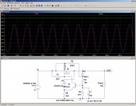
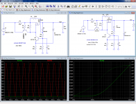
The positive regulator also works, see below: with 75V IN, it grazes the daisies, but still manages to regulate.
Most of the residual drop is in the protection resistor R1.
You get a rejection of 50dB instead of 70dB because you didn't use the normalized unity stimulus for the Bode plot: you used 12, which represents a penalty of more than 20dB.
In addition, the FDB2532 is hugely oversized for the task, which means the static rejection of 70dB quickly dregrades as frequency is increased.
Note that in a real circuit, you'd need to use proper devices: the BC337 has an insufficient Vce.
Standard precautions should also be included: a 15V G-S zener for the MOSfet, and a 1N4148 across the B-E of the small Bjt (and prehaps a small resistor in series with the 10µF)
Attachments
Is there a reason not to use the usual LM317/337 parts?
They can deliver almost any voltage, well regulated.
Jan
They can deliver almost any voltage, well regulated.
Jan
...at least unless the voltage drop won't exceed 40 V.
Otherwise I'd recommend a Maida style regulator which also can be sucessfully designed and built for negative input and output voltages, using LM337 and complimentary discrete parts.
Best regards!
Otherwise I'd recommend a Maida style regulator which also can be sucessfully designed and built for negative input and output voltages, using LM337 and complimentary discrete parts.
Best regards!
- Status
- Not open for further replies.
- Home
- Amplifiers
- Power Supplies
- Need Negative High Voltage Regulator Circuit