Coming back with more measurements. I desoldered transformers and transistors and re-measured everything.
Output transformer. Primary 2.2ohm, secondary 0.4ohm
interstage transformer. (supposed) primary 150ohm, another 650ohm winding and 100-0-100ohm secondary
Q3 and Q4 when measured EB and DB diodes both measure ~185mV
Q1 and Q2 when measured EB and DB diodes both measure ~200mV
I plan to measure input stage voltages without transformers our output transistors and see if it's still making the noise. If it doesn't, then move on the the phase splitter.
Btw, how is Q2 biased in this arrangement. 47K and 12K resistors provide base voltage, but there's also a 560K feedback resistor involved. How do we ensure bias point in reference to the emitter? I'm used to simple triode gain stage calcs with grid referenced to ground.
Cheers,
Bane
From a DC point of view, the 560k is in // with the 47k.
Calculate the divider 12k with 47k//560k
I find: Base of Q2: -1.95V.
Emitor of Q2: -1.75V.
Emitor current: 2.6mA.
Calculate the divider 12k with 47k//560k
I find: Base of Q2: -1.95V.
Emitor of Q2: -1.75V.
Emitor current: 2.6mA.
Last edited:
Did some more probing and testing with a 9V regulated power supply. The first stage supply drops the voltage to 7V though a 2.2K resistor, which means that it draws around 1mA. That should be about right I guess. The first stage on itself sounds great, clear and loud. I traced the signal to Q2 base and it's all good. Now, around Q2 is where it starts to get funny. I tried swapping transistors with the same results, so it's probably not the transistor to blame.
I connected the interstage transformer with few aligator clips and tried to measure and trace the signal.
The Q2 base sits at 1.45V. Emitter voltage wasn't easy to measure. For some reason, when I apply the signal it goes up and then it takes few minutes for the emitter capacitor to discharge and for the voltage to go down. I think it settles around 1.55V, but not sure. Maybe over time it would go lower. That seems strange, I would expect that voltage to be stable. When tracing the signal at the collector or the interstage transformer secondary winding I get quiet and very distorted sound. So it seems like it's that stage to blame.
you mean the pins? No, no numbering on the pins. I used PCB drawing to figure it out, although it's not that difficult. One winding has a center tap, so it must be the secondary. The other two are independent, so one of them is the primary. I tried both without much success.
Cheers
Cheers
Last edited:
I asked because if you have the connections to pins 5 & 6 reversed and the connections to pins 1 & 3 are straight then you could have oscillation around Q2 and the output stage due to this phase inversion . This would explain the unstable emitter voltage reading of Q2
Yes, phase issues were possible when it was all wired up. But in the last test I didn't wire the secondary of the interstage transformer at all, just clipped the primary to the rest of the circuit and scoped the output.
One interesting thing happened though, I was tracing the circuit though a battery powered amp (through a 1uF capacitor to block DC). The ground was clipped to the chassis of my deacy amp. Even without the probe capacitor touching anything in the circuit, if I slam the strings hard enough, there is some faint noise that comes though the speaker. Not sure how that's possible, only ground path is connected to the monitor amp, nothing else.
One interesting thing happened though, I was tracing the circuit though a battery powered amp (through a 1uF capacitor to block DC). The ground was clipped to the chassis of my deacy amp. Even without the probe capacitor touching anything in the circuit, if I slam the strings hard enough, there is some faint noise that comes though the speaker. Not sure how that's possible, only ground path is connected to the monitor amp, nothing else.
GOOD, and keep it until the end.Did some more probing and testing with a 9V regulated power supply.
We have already too many variables to add varying unstable power supply 🙄
Correct.The first stage supply drops the voltage to 7V though a 2.2K resistor, which means that it draws around 1mA. That should be about right I guess.
Cool.The first stage on itself sounds great, clear and loud. I traced the signal to Q2 base and it's all good.
Now, around Q2 is where it starts to get funny. I tried swapping transistors with the same results, so it's probably not the transistor to blame.
I connected the interstage transformer with few aligator clips and tried to measure and trace the signal.
Looks like if somehow R9 is open (or some trace is cut or you switched Base for Emitter and viceversa) so current though Q2 charges C5 to some peak voltage and it stays there.The Q2 base sits at 1.45V. Emitter voltage wasn't easy to measure. For some reason, when I apply the signal it goes up and then it takes few minutes for the emitter capacitor to discharge and for the voltage to go down. I think it settles around 1.55V, but not sure. Maybe over time it would go lower. That seems strange, I would expect that voltage to be stable.
But what I was starting to suggest and continue now is to go **real** step by step.
And I mean it 😀
1) feed some audio straight to speaker (from other source of course: does it sound? Clean, undistorted?
Cool.
2) now connect TR2 secondary to speaker.
apply audio to TR2 primary (nothing else connected to it of course), ground one terminal, alternatively apply signal to other two ... do you get sound on speaker?
3) Connect Q3 emitter to R13, its base to one of TR1´s driver windings, center tap to biasing divider , just in case only the two resistors in Deacy´s schematic, leave Thermistor out for a later tweaking, apply DC.
Measure DC, Base and Emitter voltage.
Then apply signal to Tr1 primary.
You *should* hear some relatively loud nasty tone through speaker.
Buzzy because it´s just half a class B caused sinewave, but loud and clear.
If you had a scope, you shoud clearly see half a sinewave, probably still showing crossover distortion but that is not the main point.
4) if all works, meaning we tested both power transistor health and transformer ability capable of driving it, we repeat same with the other power transistor.
5) if both work, now we connect both and drive primary of T1, we should get a loud sinewave at the speaker out.
Nastu, funky, but recognizable, and at least some 200mW RMS.
I´d be happy to reach this stage at least for now.
For sinewaves, download and play:
set MP3 player to Loop or repeat one, so you have continuous tone (with a small glitch every 30 seconds).
Any headphone out will giv you 100 to 200mV RMS, and is enough to drive T1, at least for testing.
If you don´t have a scope available, I´ll link to "how to" use a free Software Scope with a Notebook plus the needed attenuator.
Good luck.
When tracing the signal at the collector or the interstage transformer secondary winding I get quiet and very distorted sound. So it seems like it's that stage to blame.
JF is probably right about the emitter resistor being open. To test for that short across the capacitor C5. Then if that is not it try flipping around TR1's windings between Q2 and power.
Last edited:
thanks all for your help, I will try the suggested.
This turned out to be the most problematic build so far, and I've built many tube amps, preamps, pedals... 🙂
This turned out to be the most problematic build so far, and I've built many tube amps, preamps, pedals... 🙂
Finally some good news!
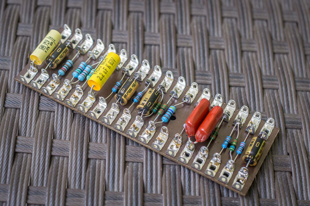
I followed the advice, took it apart and tested stage by stage. There were two issues - bad joint at R9 (as suggested) that prevented Q2 from being biased properly. The second issue were flipped primaries (or secondaries) which resulted in positive instead of negative feedback. That caused the mechanical noise. After I figured that out, I put it back together and it fired up. There's only one more problem - this thing is super loud! Through an efficient Celestion G10 Vintage, it's just too loud for my apartment. It's clean with guitar volume set around half and gets dirty as you go up. The distortion gets creamy and slightly wooly rather than harsh and buzzy which is a good thing. Now I'll have to get a less efficient speaker or run it into dummy load and tap the signal for direct recording, it's way too loud as is 🙂
Here's a photo of the point-to-point board, don't have one of the finished box yet. It's an ugly sheet metal enclosure. I'm thinking about doing something creative with it, just not sure what yet 🙂
Thanks again for the help and for awesome tips on debugging, it really payed off.
Last edited:
Glad you found it 🙂
Mike the speaker for recording, tapping output leaves much of the magic out 🙂
Mike the speaker for recording, tapping output leaves much of the magic out 🙂
I thought the original was used as "a pedal": dummy load and line out.
That's a fairly powerful amp. I'm not shocked that with a good speaker it will annoy the neighbors several houses away.
That's a fairly powerful amp. I'm not shocked that with a good speaker it will annoy the neighbors several houses away.
Cool.
Do you want to lower the gain ?
This is easy: Remove a capacitor on a emitter resistance, or split a emitter resistance to have one with capacitor, the other without.
Do you want to lower the gain ?
This is easy: Remove a capacitor on a emitter resistance, or split a emitter resistance to have one with capacitor, the other without.
I wouldn't want to reduce gain, it's nice that it overdrives the output stage a little bit. Which leaves me with using a less efficient speaker, dummy load or maybe attenuator.
Cheers,
Bane
Cheers,
Bane
I agree with cbdb. Guitar amps need a high input impedance yours is about 10K when greater than 100K is required. A Cheap TL072 JFET preamp is ideal.
To increase the input impedance AND decrease the gain, you can do as I mentioned about lowering the gain, doing it at the input transistor emitter.
You can (should) leave amp as is, and simply add a resistor in series with input, pick your value between 10k and 100k or add a pot or trimmer to find desired value by ear.
This will both lower gain and rise input impedance as seen by the guitar with the minimum effect on amplifier ooerating point.
To those trying, in good faith, to "improve" this amplifier, that is not the point, **this** particular circuit was used to help achieve a particular famous sound, that of Queen´s guitar player Brian May.
If Bancika wanted to make "a good guitar amplifier" he´d plain make something else, not the goal here.
As an example which will cause modern Engineers a mental breakdown, this is the Dallas Arbiter made "Rangemaster" Treble Booster, the secret weapon used by none less than Eric Clapton, Ritchie Blackmore, and countless others to achieved liquid sustain when used between guitar and tube Marshall amplifier ... played full blast with all knobs on 10, of course:
Notice the use of earliest transistors available, ridiculous small input and output coupling capacitors, scratchful volume pot with full DC passing through it, terrible specs Germanium transistor and positive ground which makes it unusable with the currently standard 9V pedalboard shared supply.
Just calculate the input impedance 😉
In fact "Deacy" was a homemade DIY way to somehow duplicate the Rangemaster out of junk parts lying around.
FWIW Brian May was a poor but ingenious guy, who made his own guitar and wound his own pickups. 🙂 🙂
And this is the sound he achieved:
YouTube
Last edited:
- Status
- Not open for further replies.
- Home
- Live Sound
- Instruments and Amps
- Need help with simple germanium amplifier