I think you may be making the solution to this problem harder than it has to be.interesting idea, thanks.
The Scott runs the 12ax7 tubes at lower than spec voltages on the filaments and they live very long lives.
The Telefunkens work very well in this environment and are likely fine, and worth a few bucks. So check them for continuity between pins 4 and 5, and if they have it, put them back in.
I'd start by cleaning all the 12ax7 tube sockets in the amplifier and re-tensioning the pin sockets.
Contact cleaner or isopropyl alcohol can be used along with intertooth dental cleaning brushes.
A jewelers screwdriver or similarly sized pick will work to restore the pin sockets.
A small amount of deoxit D5 will help with oxide removal as a final step
It would also be a good idea to clean and re-tension all the sockets after you figure out where the open circuit is with filament supply.
After addressing the 12AX7 sockets you can use your multimeter to track the wire (probably purple in color) that should run from the bias cap to pin 5 of V102. You should have -43Volts at both ends of the wire.
You can look for the open circuit with the rectifier tube removed so there won't be high voltage worries as you're searching.
If that's good and you have -43volts at that location, continue checking the voltage across pins 4 and 5 of all 4 12AX7's until you find where the voltage reading stops. It should be dropping by about 11 volts per tube as you go down the chain.
Hope this helps !
Thanks for the kind suggestions! Turns out that even though I correctly attached all the bias cap positive leads together, I neglected to ground them! Lol.I think you may be making the solution to this problem harder than it has to be.
The Scott runs the 12ax7 tubes at lower than spec voltages on the filaments and they live very long lives.
The Telefunkens work very well in this environment and are likely fine, and worth a few bucks. So check them for continuity between pins 4 and 5, and if they have it, put them back in.
I'd start by cleaning all the 12ax7 tube sockets in the amplifier and re-tensioning the pin sockets.
Contact cleaner or isopropyl alcohol can be used along with intertooth dental cleaning brushes.
A jewelers screwdriver or similarly sized pick will work to restore the pin sockets.
A small amount of deoxit D5 will help with oxide removal as a final step
It would also be a good idea to clean and re-tension all the sockets after you figure out where the open circuit is with filament supply.
After addressing the 12AX7 sockets you can use your multimeter to track the wire (probably purple in color) that should run from the bias cap to pin 5 of V102. You should have -43Volts at both ends of the wire.
You can look for the open circuit with the rectifier tube removed so there won't be high voltage worries as you're searching.
If that's good and you have -43volts at that location, continue checking the voltage across pins 4 and 5 of all 4 12AX7's until you find where the voltage reading stops. It should be dropping by about 11 volts per tube as you go down the chain.
Hope this helps !
My mind races three moves ahead while my hands stutter and fumble.
So everything glows but the rectifier, which will be an adventure for another day. Have a great day folks!
Okay folks, I was feeling confident (always a mistake) and thought I'd go straight to DC bias instructions per HH Scott. Made my RCA cable, pulled V3, hooked up a speaker, plugged into tuner yada yada yada, went to turn the volume up and i got super loud scratchy volume pot sounds. Then I realized I never checked any voltages with the rectifier installed. duh. I pulled the output tubes, put the amp on it's side hooked up my probes and measured 454VDC at pin 3 of V4 ... and then R207 smoked.
Oh yeah! I reflowed the connections on the bias adjust switch after attempting to balance tubes due to a sizzle and pop centered around C208 more or less.
Last edited:
Scratchy volume pots usually is related to leaky grid coupling capacitors. Are all the critical capacitors renewed?
Since you have done a lot of work on this unit you might need to be more systematic in getting confidence in all the changes. Do you have a variac? They are cheap second hand, and you can generally sell them for what you paid for them, bar the postage.
Since you have done a lot of work on this unit you might need to be more systematic in getting confidence in all the changes. Do you have a variac? They are cheap second hand, and you can generally sell them for what you paid for them, bar the postage.
Morning Hector! I'll NEVER sell my Variac. I've been using it but to check B+ the unit needs 117VAC. I thought I replaced all the electrolytics but I left some ceramics in there as well as the PECs. My 4uf Wimas wouldn't fit so I used what I had; some 85 degree rated electrolytics. It looks like I hit C203 "triangle" with my soldering iron so probably causing a short in it causing R207 to overheat. Aaaarghh! I'll order some parts, any suggestions? Thanks again!Scratchy volume pots usually is related to leaky grid coupling capacitors. Are all the critical capacitors renewed?
Since you have done a lot of work on this unit you might need to be more systematic in getting confidence in all the changes. Do you have a variac? They are cheap second hand, and you can generally sell them for what you paid for them, bar the postage.
c26 and c126 are 25uf/50v npo sprague atom axials and i don't remember if they're new or original...
Since Digital Multimeters are inexpensive and widely available today, its relatively easy to set the output tube bias on this vintage Scott amp.Okay folks, I was feeling confident (always a mistake) and thought I'd go straight to DC bias instructions per HH Scott. Made my RCA cable, pulled V3, hooked up a speaker, plugged into tuner yada yada yada, went to turn the volume up and i got super loud scratchy volume pot sounds. Then I realized I never checked any voltages with the rectifier installed. duh. I pulled the output tubes, put the amp on it's side hooked up my probes and measured 454VDC at pin 3 of V4 ... and then R207 smoked.
The LK72B provides a 3.3 ohm 2watt current sensing resistor in series with the cathode ground connection for each channel's pair of output tubes.
There are also pots provided for adjusting bias voltage and DC Balance for each channel.
Working from under the chassis, I have found this adjustment method to work pretty well:
1) Attach a speaker or resistive load to output terminals you'll listening with.
2) Turn the bias adjust pots all the way counter clockwise and then clockwise about 1/4 turn.
3) Turn the balance pots to their midway position.
4) Set multimeter to DC voltage 750 volts or higher.
5) Using some type of leads with clips at the end, attach multimeter leads between the plate connections on the two Power tube sockets of one the channels.
6) Rotate the Balance pot for the channel under adjustment to get as close to 0 Volts as you can.
The indicated voltage will be floating around as you do this, and as you get near 0 Volts you can lower the voltage setting on your multimeter for greater sensitivity. I find the meter reading will be appear stable at the 20 Volt meter scale and too unstable to be useful below this.
7) When you get the first channel close to 0 Volts, do the same to the other channel.
8) When the DC balance is set for both channels set your multimeter scale to 2 Volts and measure the voltage drop across the 3.3 ohm resistor for each channel's cathode ground wire.
Adjust the bias voltage pot to .23/.24 volts for each channel.
You will need to go in small increments and go back and forth between channels as you do this, since the channels will effect each other as you vary the bias voltage.
You will also need to be monitoring the channel balance and adjust it as you vary the bias voltage
The ,23/.24 voltage drop will give a 70ma current value for each pair of output tubes, and with the DC balance adjusted to 0 Volts, you'll have 35ma per tube which is what Scott specified.
The published spec for the US made 7591's was 38ma so there is room for some drift over time, and it provides for longer tube life at 35ma.
The Russian Tung-Sol tubes are rated for lower plate power dissipation and should be adjusted slightly below 35ma, so a little current drift doesn't put them in an unsafe operating environment.
I would go thru the procedure getting close to the values specified initially, and then allow the amp to operate for an hour or two before spending a lot of time getting final adjustments as close as you can.
I find my line voltage to constantly vary about 3 VAC and it will change the plate current from 35ma to 33ma as it does this.
I monitor the line voltage as I make adjustments, and set 35ma value when it its close to maximum.
The entire process can be done from the top of the chassis if you install individual 10ohm plate sensing resistors and test point jacks in place of the 3.3ohm resistors.
But that's a story for a different day !
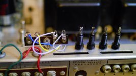
Thank you Ponchonova for the most clear and lucid explanation on this I've read yet. Picture below are my connections to the 10 ohm resistors and my test jacks I can't use as they are too large. I have clips for my test leads so I'm good. Blue, yellow, violet and grey; maybe should have used brown instead of violet. Thank you so much Ponchonova, I appreciate your help!Since Digital Multimeters are inexpensive and widely available today, its relatively easy to set the output tube bias on this vintage Scott amp.
The LK72B provides a 3.3 ohm 2watt current sensing resistor in series with the cathode ground connection for each channel's pair of output tubes.
There are also pots provided for adjusting bias voltage and DC Balance for each channel.
Working from under the chassis, I have found this adjustment method to work pretty well:
1) Attach a speaker or resistive load to output terminals you'll listening with.
2) Turn the bias adjust pots all the way counter clockwise and then clockwise about 1/4 turn.
3) Turn the balance pots to their midway position.
4) Set multimeter to DC voltage 750 volts or higher.
5) Using some type of leads with clips at the end, attach multimeter leads between the plate connections on the two Power tube sockets of one the channels.
6) Rotate the Balance pot for the channel under adjustment to get as close to 0 Volts as you can.
The indicated voltage will be floating around as you do this, and as you get near 0 Volts you can lower the voltage setting on your multimeter for greater sensitivity. I find the meter reading will be appear stable at the 20 Volt meter scale and too unstable to be useful below this.
7) When you get the first channel close to 0 Volts, do the same to the other channel.
8) When the DC balance is set for both channels set your multimeter scale to 2 Volts and measure the voltage drop across the 3.3 ohm resistor for each channel's cathode ground wire.
Adjust the bias voltage pot to .23/.24 volts for each channel.
You will need to go in small increments and go back and forth between channels as you do this, since the channels will effect each other as you vary the bias voltage.
You will also need to be monitoring the channel balance and adjust it as you vary the bias voltage
The ,23/.24 voltage drop will give a 70ma current value for each pair of output tubes, and with the DC balance adjusted to 0 Volts, you'll have 35ma per tube which is what Scott specified.
The published spec for the US made 7591's was 38ma so there is room for some drift over time, and it provides for longer tube life at 35ma.
The Russian Tung-Sol tubes are rated for lower plate power dissipation and should be adjusted slightly below 35ma, so a little current drift doesn't put them in an unsafe operating environment.
I would go thru the procedure getting close to the values specified initially, and then allow the amp to operate for an hour or two before spending a lot of time getting final adjustments as close as you can.
I find my line voltage to constantly vary about 3 VAC and it will change the plate current from 35ma to 33ma as it does this.
I monitor the line voltage as I make adjustments, and set 35ma value when it its close to maximum.
The entire process can be done from the top of the chassis if you install individual 10ohm plate sensing resistors and test point jacks in place of the 3.3ohm resistors.
But that's a story for a different day !
Attachments
I still have to add the missing wire from c21 to c22 and find out what went wrong with my bias supply. The cap seems to be charging at the same rate as the others (C203 triangle) so I'll pull the 5ar4 and check my v drops.
I just got done adding 10ohm sensing resistors to my LK72B.Thank you Ponchonova for the most clear and lucid explanation on this I've read yet. Picture below are my connections to the 10 ohm resistors and my test jacks I can't use as they are too large. I have clips for my test leads so I'm good. Blue, yellow, violet and grey; maybe should have used brown instead of violet. Thank you so much Ponchonova, I appreciate your help!
I used the Real Estate occupied by the original Scott Hum and pop system to install the necessary hardware.
Here is how I went about it:
I took out the wiring, resistors, and caps associated with Scott bias check system.
I removed the two RCA jacks used for bias checking and installed two test point jacks at that location.
I used the Scott DPDT switch which I had stripped earlier and ran the current sensing wires to the switch.
The right channel went to the right fwd and aft terminals of the switch.
Likewise I attached the left channel sensor wires to the left side switch terminals.
The two center switch terminals were connected to the two test point jacks.
I also drilled an additional hole and added a test point jack for the ground.
Checking the DC balance now involves moving the switch to the left or right , inserting the meter probes into the the two test point jacks and adjusting to 0 volts using the Balance pot.
The voltage reading is much more stable this way than by measuring plate voltage and I use the 2 Volt scale.
Once the balance is zeroed out, taking out one of the meter probes and inserting it into the ground test point jack allows a direct reading and adjustment of the bias current.
Easy Peezey !
Attachments

- Home
- Amplifiers
- Tubes / Valves
- Need help with poorly built HH Scott LK72B