A quick look at the schematic suggests a comparatively simple fix for problems with replacement 7591s.
Change C27, C29, C127, & C129 to 600+ WVDC/0.22 μF. parts; either 716P series Orange Drops or Soviet surplus K40 paper in oil (PIO) should do nicely.
Change R42, R43, R142, & R143 to 220 Kohms. For low noise, metal film parts are indicated here.
The resistance value change should improve the situation regarding current production 7591s "disliking" an out of spec. grid to ground value. The cap. value change is a consequence of the resistance value change. It prevents loss of low frequency info.
I don't do simulations. Perhaps Koonw would run a simulation, with the suggested parts value changes.
I'm going to completely contradict Eli here and suggest you stick to the original design as Scott designed it.
The thevenin equivalent resistance worst case in the grid circuit is 210K which is well below the 300K maximum listed in the specification of the JJ7591.. The 7591 was designed for a maximum of 300K in the grid circuit.
Run as is once sorted out.
I also don't agree with the use of partial cathode bias.
I've worked on a lot of 299C and 299D with their original 7591 which were still in reasonable condition after decades of use. (And yes I have seen ones that were completely cooked.)
I would recommend restuffing the bias and filament supply filter capacitor if you are motivated. These are common + (backwards from standard cans) and were custom made for HH Scott. It will be tidier..
Really important to get a well matched and burned in set of 7591 output tubes, this will help weed out the infant mortality failures and assure good balance.
Setting the bias using the provided TP is only part of the job, as I recall setting the DC balance needs to be done with a distortion analyzer which likely you don't have. (You adjust for lowest distortion at some specified power level IIRC.) Something you could consider would be to replace the 3.3 ohm cathode resistor with two separate 6.81 ohm resistors (1%) one per cathode, adjust DC balance for matching voltage drop and then optionally jumper them together. (At these values it probably will not make a difference.)
I'm going to completely contradict Eli here and suggest you stick to the original design as Scott designed it.
The thevenin equivalent resistance worst case in the grid circuit is 210K which is well below the 300K maximum listed in the specification of the JJ7591.. The 7591 was designed for a maximum of 300K in the grid circuit.
I did state a quick look. 😉 No, I did not run any numbers. I've no reason to question Kevin. The matter can be brought up again, if and when replacement O/P tubes run away.
Unfortunately not entirely unlikely either with modern tubes.... Scott ran pretty high plate voltages in their designs, and those tubes could take it.
Thank you kevinkr, Eli Duttman and Koonw.
I'm trying to get in the proper mindset to do this....fear sucks.
I'm trying to get in the proper mindset to do this....fear sucks.
Greetings and salutations! I'm still alive and working the problem. I've restored it to "stock" as best I can tell with some caveats. One bias pot was damaged so replaced all 4 with 10 turn 20k ohm units and added 14 ohms resistance after 33ohm 5watt resistor (R205) in bias supply.
I haven't tested anything with 5AR4 installed but here's where I am. I set all the pots at midway (5 turns) and have -18v more or less on pin 6 of 7591a's. My 6U8a's glow, 7591a filaments are good but my 12AX7 string is dark and cold. Measuring DC, I read -42volts between pins 4 V1 and 5 V102. I reflowed and checked again the connections and correct me if I'm mistaken but shouldn't I have some glow even with 10.5 volts per tube? I pulled each 12AX7 and tested the filaments for continuity pin 4 to 5 and all tests good. I missed something obvious didn't I? I'll check back but first I must look through my stash for 4 more 12AX7s. Thanks in advance for your help!
I haven't tested anything with 5AR4 installed but here's where I am. I set all the pots at midway (5 turns) and have -18v more or less on pin 6 of 7591a's. My 6U8a's glow, 7591a filaments are good but my 12AX7 string is dark and cold. Measuring DC, I read -42volts between pins 4 V1 and 5 V102. I reflowed and checked again the connections and correct me if I'm mistaken but shouldn't I have some glow even with 10.5 volts per tube? I pulled each 12AX7 and tested the filaments for continuity pin 4 to 5 and all tests good. I missed something obvious didn't I? I'll check back but first I must look through my stash for 4 more 12AX7s. Thanks in advance for your help!
Okay, swapped in 4 known good Baldwin 12AX7s ... nothing after 60 seconds I shut off the power. Any thoughts?
Could it be the polarity of the can cap C203? Was that replaced, if it is old? It could be that it is the reverse to what you expect, so that it creates a negative rail for the bias.
Thanks Hector! I replaced C203 with 4 individual caps and grounded the positive leads. Did that a year ago, time flies.Could t be the polarity of the can cap C203? It could be that it is the reverse to what you expect, so that it creates a negative rail for the bias.
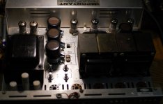
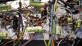
I posted a few pictures a year ago but no one thought them particularly helpful. It's a rat's nest of wire and it hurts my head to look at it. I'll take some new pictures and post them.Maybe a couple of pictures could help?
If those pictures are still relevant - did you disconnect the old can caps when you added the new seperate ones? It looked like they were using the tags on the old can.

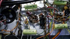
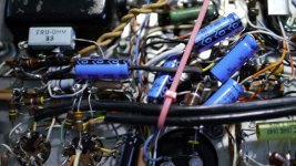
Hector, I used a ground lug from a new cap (32/32uf 525v) to ground the positives of the bias supply caps; is that wrong?
Series heaters make it a bt more difficult since just one dodgy pin connection would impact all 4 tubes. Not sure if this is the right approach, but I would leave the tubes out and temporarily fix an equivalent resiistor across the start and end of the chain so I could verify the supply was OK. The current is 300mA, and there are 43v across the 4 heaters, so the resistor should be 43/.3, so roughly 120R, and power rated 0.3 x 43, so 15W as a min. Maybe you could build up something with higher wattage resistors linked together, parallel and series? It is probably an over the top way to do it, but it allows you to divide the problem in half.
I'm not an expert here by any means, but I have a similar project to this waiting for me, so interested in your progress here. Mine is not quite such a nest of wires underneath, but it is integrated and does have a lot of controls for various things, that add to the complexity.
If it was a new cap then that is OK, but did you nte the earlier comment that the Scott caps were reversed to normal caps with a positive case?
If it was a new cap then that is OK, but did you nte the earlier comment that the Scott caps were reversed to normal caps with a positive case?
I'm not an expert here by any means, but I have a similar project to this waiting for me, so interested in your progress here. Mine is not quite such a nest of wires underneath, but it is integrated and does have a lot of controls for various things, that add to the complexity.
If it was a new cap then that is OK, but did you nte the earlier comment that the Scott caps were reversed to normal caps with a positive case?
interesting idea, thanks.Series heaters make it a bt more difficult since just one dodgy pin connection would impact all 4 tubes. Not sure if this is the right approach, but I would leave the tubes out and temporarily fix an equivalent resiistor across the start and end of the chain so I could verify the supply was OK. The current is 300mA, and there are 43v across the 4 heaters, so the resistor should be 43/.3, so roughly 120R, and power rated 0.3 x 43, so 15W as a min. Maybe you could build up something with higher wattage resistors linked together, parallel and series? It is probably an over the top way to do it, but it allows you to divide the problem in half.
- Home
- Amplifiers
- Tubes / Valves
- Need help with poorly built HH Scott LK72B