Hello people.
I've reached that stage in my project where I doubt my work, my self and my ability to follow though.
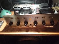
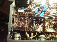
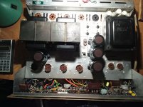
Picked this up for $50.00. In trying to find the proper schematic I realised the builder wasn't focused.
Now I've built a pair of Eico hf30 clones from some Baldwin amps I acquired; survived their spark tests
and I even kept all the smoke in them! So I can read a schematic. Back when I had a Metcal and Pace I
could solder but now I'm using a stained glass soldering iron (don't ask).
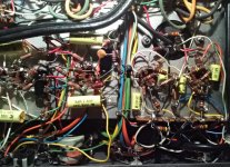
So....if you don't mind, please examine the pictures and let me know f you see something I missed or that doesn't make sense.
(I stopped working on it about a three years ago!)
Thank you in advance,
Respectfully yours,
Todd
I've reached that stage in my project where I doubt my work, my self and my ability to follow though.
Picked this up for $50.00. In trying to find the proper schematic I realised the builder wasn't focused.
Now I've built a pair of Eico hf30 clones from some Baldwin amps I acquired; survived their spark tests
and I even kept all the smoke in them! So I can read a schematic. Back when I had a Metcal and Pace I
could solder but now I'm using a stained glass soldering iron (don't ask).
So....if you don't mind, please examine the pictures and let me know f you see something I missed or that doesn't make sense.
(I stopped working on it about a three years ago!)
Thank you in advance,
Respectfully yours,
Todd
Pictures
nt
nt
Attachments
-
 IMG_20210111_045946.jpg535 KB · Views: 302
 -
 IMG_20210111_050158.jpg926.2 KB · Views: 303
 -
 IMG_20210111_050413.jpg805 KB · Views: 292
 -
 IMG_20210111_052033.jpg464.3 KB · Views: 298
 -
 IMG_20210111_052128.jpg608 KB · Views: 292
 -
 IMG_20210111_052140.jpg574.3 KB · Views: 211
 -
 IMG_20210111_052149.jpg535.3 KB · Views: 188
 -
 IMG_20210111_052424.jpg967.5 KB · Views: 185
 -
 IMG_20210111_052441.jpg530.5 KB · Views: 182
 -
 IMG_20210111_052654.jpg561.6 KB · Views: 188
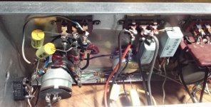
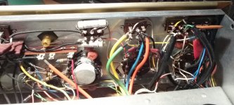
No one could possibly diagnose a problem based on pictures, but folks who've seen a few kit builds from the Golden Age can offer a few suggestions.
In lots of cases, including this one, soldering was too timid, and proper solder flow is rare. Some will recommend removing the existing solder, and re-soldering, and sometimes this is best. But as you get experienced you'll get to the point where you can add solder to the existing too-cool joint, carry away excess on the soldering iron, and watch the joint repair itself.
You'll want to re-solder *all* solder joints in this machine, based on the visible ones. Let each joint reach temperature for a smooth concave flow, and remove heat. Remove valves before soldering their sockets of course.
Any Weller 40 Watt iron can do the job just fine; doesn't need anything fancy; the music's not in the guitar, it's in your fingers. This seems like a good machine to practice on and get your confidence back. Give it some Love.
YOS,
Chris
Thank you, Chris and Eli. I appreciate your input.
I'll probably get that Hakko with tips for $129.99,
And the illuminated magnifier...
Ka-ching!
I'll probably get that Hakko with tips for $129.99,
And the illuminated magnifier...
Ka-ching!
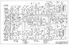
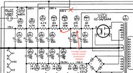
The schematic is here if you need it and you can measure the actual voltages against the schematic.
http://hhscott.com/pdf/fs/LK72B.JPG
http://hhscott.com/pdf/fs/LK72B.JPG
Attachments
Last edited:
Thanks Koonw. Is it still good practice to adjust the variac so that the filament voltage is 6.3v before taking other measurements?
Code:
Thanks Koonw. Is it still good practice to adjust the variac so that the filament voltage is 6.3v before taking other measurements?
Last edited:
Thanks Koonw, will do!
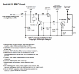
Do you (or anyone else) have any thoughts on Dave's Enhanced Fixed Bias mod, from that other website? Cooler tubes seems GOOD to me.
Do you (or anyone else) have any thoughts on Dave's Enhanced Fixed Bias mod, from that other website? Cooler tubes seems GOOD to me.
You'll need to share some details on that mod, I have no idea what other site you are referring to, there a number of them.. LOL Scott ran their outputs quite hard but running the output stage at much lower than design current will probably affect the sound quality and distortion performance to some extent.
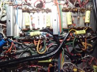
Do you have the original 7591 or replacements and if so which? (not all are created equal.)
There are replacements from EH (New Sensor) and JJ, apparently both are somewhat unreliable (not unusual for modern tubes) The JJ appears to be the one to get at this point. Check clearances to make sure what ever you buy will physically fit in the available space, Scott was not generous with space for the output tubes. Buy tested and burned in tubes if at all possible when the time comes.
I worked on a lot of 299s and a small number of 296 (still I think the best Scott integrated) decades ago, and not at all recently. Owned a couple of each. Never had a Scottkit 72B although I recollect repairing at least one.
kevinkr, thanks for joining in!
Audiokarma
Dave Gillespie's Enhanced Fixed Bias
Article: Installation of the EFB(tm) Bias Circuit in a Dynaco ST-35
The 270 ohm 5 watt resistor should be 500 ohms, I believe...
What do you think?
Audiokarma
Dave Gillespie's Enhanced Fixed Bias
Article: Installation of the EFB(tm) Bias Circuit in a Dynaco ST-35
The 270 ohm 5 watt resistor should be 500 ohms, I believe...
What do you think?
Attachments
kevinkr
All original tubes. I know it never functioned correctly but I don't know if it's been damaged by running it in its incomplete state.
All original tubes. I know it never functioned correctly but I don't know if it's been damaged by running it in its incomplete state.
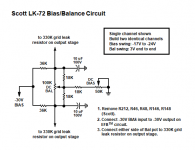
Current production 7591s are intolerant of taking liberties with the grid to ground resistance limit. The 7591 datasheet shows a max. of 300 K, when "fixed" bias is employed. Unlike the 12AX7 section found in many Fisher models, the "concertina" phase splitter triode in the LK72B will be fine working into a resistance that complies with the published limits.
An alternative to lowering the total grid to ground resistance is employing combination bias. "Standing" the 7591 cathodes, either singly or in pairs, on 100 Ω/470 μF. bias networks stabilizes operating conditions and provides a convenient "idle" current test point.
An alternative to lowering the total grid to ground resistance is employing combination bias. "Standing" the 7591 cathodes, either singly or in pairs, on 100 Ω/470 μF. bias networks stabilizes operating conditions and provides a convenient "idle" current test point.
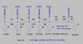
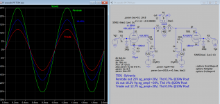
Here are psu, output stage and bias simulations, hope this helps.
Attachments
Last edited:
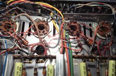
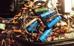
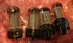
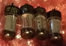
Eli, thanks again! here's a shot of my output tubes. Scott branded...
Westinghouse perhaps? Getters seem good. 9-pins are all Telefunken but every time I look at them the lettering falls off! Did you look at the sim?
Westinghouse perhaps? Getters seem good. 9-pins are all Telefunken but every time I look at them the lettering falls off! Did you look at the sim?
Attachments
Koonw, thanks for generating the sim!
The B+ voltages seem right (if I understand)
No ultralinear taps. Is it worth putting in a switch for triode mode?
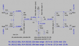
As for the bias voltages... with the 50k pot, it'll only adjust from -20.27 to -23.89?
So i would change the DC bias pots to 10k for max flexibility?
If that's true, how twitchy would that be to adjust?
Of course, if I'm totally confused I hope you'll try and set me straight!
The B+ voltages seem right (if I understand)
No ultralinear taps. Is it worth putting in a switch for triode mode?
As for the bias voltages... with the 50k pot, it'll only adjust from -20.27 to -23.89?
So i would change the DC bias pots to 10k for max flexibility?
If that's true, how twitchy would that be to adjust?
Of course, if I'm totally confused I hope you'll try and set me straight!
Yes, the range is not wide, you can get wider bias range (-17.4v to -27.2v) when you change the value of R210 from 22k to 10K or so. Or parallel it with 18k or so. If the output impedance is too high to drive your speaker then you can consider UL and triode model. For triode it's simply connect the screen to the anode with a small resistor, for UL you need UL tap.
Edit: wider bias range (-19.7v to 27.2v)
Previous snap should read:
R1 (R212) 82k, R14 (R210) 10k bias range -19.7v to -27.2v mid -23v
R1 (R212) 82k, R14 (R210) 22k bias range -17.4v to -23.8v mid -23v
Edit: wider bias range (-19.7v to 27.2v)
Previous snap should read:
R1 (R212) 82k, R14 (R210) 10k bias range -19.7v to -27.2v mid -23v
R1 (R212) 82k, R14 (R210) 22k bias range -17.4v to -23.8v mid -23v
Last edited:
- Home
- Amplifiers
- Tubes / Valves
- Need help with poorly built HH Scott LK72B