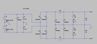
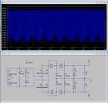
I am trying to see the effect of the DC voltage filtering if I were to use CRC filter. I have drawn the simulation, but it does not seem to be working. I also wanted to check on the effectiveness of the snubber capacitors right at the transformer AC secondary coils.
Any help will be greatly appreciated!
Thanks in advance,
Pavlo
Any help will be greatly appreciated!
Thanks in advance,
Pavlo
Attachments

Thank you! Fixed that!
Now, the voltage for some reason is only 26V instead of 35V as it need to be???
Now, the voltage for some reason is only 26V instead of 35V as it need to be???
Last edited:
Wow! - adding 1 ohm resistor reduces ripple by a lot! Unfortunately it also drops the voltage....
Before the R the ripple is between 33.97V and 33.72V => 0.25V or 250 mV. After the R, ripple is between 33.505V and 33.480V => 0.025V or 25mV.
I wonder how to calculate the current flowing thru the 1 ohm resistor? What power rating should I choose? I am using this psu to power LM3886 based amp.
Attached is the sim file just in case someone needs.
Attachments
Last edited:
CRC power supplies can be analyzed with Ohm's Law. With an understanding of Ohm's Law, the voltages and current can be easily calculated.
Here are two websites among many that I found after a quick search that explain Ohm's Law:
https://www.build-electronic-circuits.com/ohms-law/
https://www.electronics-tutorials.ws/dccircuits/dcp_2.html
I suggest you have a go at learning Ohm's Law. It is a simple but very useful equation in diy electronics. LTSpice is handy for circuit simulations but a basic understanding of electricity and Ohm's Law is the foundation and starting point of electrical knowledge.
Since you know how to build circuits in LTSpice, you can use it as an aid in your education. Start with simple DC circuits and compare your calculated results using Ohm's Law with the LTSpice results.
I'm sure there are many diyAudio members that will answer any questions that you may have once you start exploring Ohm's Law.
By the way, most of the voltage drop of your circuit is from the voltage drop across the rectifier diodes. The voltage drop across the 1R resistor is small in comparison.
🙂
I guess I have one unknown in the equation - that is resistance for the LM3886 chip for power supply rails...
In simulation I used 100 ohm resistors as the load.
In simulation I used 100 ohm resistors as the load.
Or if you know the current draw of the chip, you can use Ohm's Law to calculate the resistor value for the power supply simulation, knowing the power supply voltage and current draw.
Power supply voltage +/- 35V
Io Output Current Limit |V+| = |V−| = 20V, tON = 10 ms, VO = 0V Typical 11.5 Limit 7 A (min)
R = V/I
R = 35/11.5 = 3 ohms
R = 35/7 = 5 ohms
or should I divide the current between two rails of the power supply? so it will be 6 ohms and 10 ohms?
Looks like the resistance is too small.... or did I grab wrong spec from the datasheet?
Last edited:
if you move the mouse over the component, and keep the alt key pressed you can plot the power of the deviceI guess I have one unknown in the equation - that is resistance for the LM3886 chip for power supply rails...
In simulation I used 100 ohm resistors as the load.
A CRC power supply is probably not the best for a LM3886 amplifier as its current draw varies. At rest the current is very low and at maximum output the current is very high. For instance the 1 Ohm resistor in your LTSpice simulation drops 0.05V if the quiescent current of the amplifier is 50mA, but if the maximum current is 7A (I don't know if that is the maximum for your operating point) then the resistor drops 7V.
Ideally you would not want any power supply voltage drop at all during the operation of the amplifier. The simplest supply when constant voltage is required over a wide range of current draw is to have an adequately sized transformer and enough capacitance to minimize ripple. So no CRC but only C.
Ideally you would not want any power supply voltage drop at all during the operation of the amplifier. The simplest supply when constant voltage is required over a wide range of current draw is to have an adequately sized transformer and enough capacitance to minimize ripple. So no CRC but only C.
That helped.if you move the mouse over the component, and keep the alt key pressed you can plot the power of the device
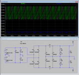
Two 10,000uF capacitors give voltage in the range from [32.3V to 33.3V] - that is 1V difference.
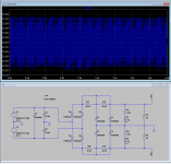
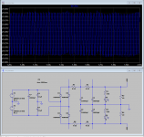
Adding four 0.22R resistors (RCRC filter) reduces the voltage variation to [29.08V to 29.63] - that is 0.55V difference.
Adding two 0.22R resistors (CRC filter) reduces the voltage variation to [31.32V to 31.97] - that is 0.65V difference.
DC current max for 0.22R 5W is I = sqrt(5/0.22) = 4.7673 Amps. Since chip consumes AC we convert by RMS ??? - 4.7673*1.41= 6.7419 Amps per rail?? Is that correct?
I don't think that adding resistor to the filter is making much sense for my particular application of the power supply. Any other opinions?
Attachments
Ideally you would not want any power supply voltage drop at all during the operation of the amplifier. The simplest supply when constant voltage is required over a wide range of current draw is to have an adequately sized transformer and enough capacitance to minimize ripple. So no CRC but only C.
After simulating multiple scenarios, I think that you are right and I don't need that R in the filter.
You are never going to get 11.7 Amps except with precision abuse.Power supply voltage +/- 35V ... Io Output Current Limit ... Typical 11.5 Limit 7 A (min)
For class AB power amps, you don't even need the power draw of THIS chip. They all run very close to theory.
You can figure the loading by basic principles. The chip can deliver 68 Watts. To do so it will dissipate about half of that, 35 Watts. (Ideal AB Efficiency is 78%, but IRL somewhat below 70%.) So you have 105 Watts sucked out of +/-35V or 70V. 105W/70V is 1.5Amps. 70V/1.5A is equivalent 105 Ohms, or 52 Ohms each side of the bipolar power.
Remember the 1.5Amps is averaged over a cycle. The peak current is 4.2 Amps, but the main filter caps will average that out.
That's FULL ROAR. You typically won't play loud parts that loud long enough to matter (a few mS peaks per track). Average over a track, even rock/disco without much added clipping, is 12dB lower, So the current is 1/4th and the equivalent resistance is 4X, or 200r/rail.
You typically complain about buzz at very low level. Now you do want data on the specific chip. Except for all AB BJT stages you can wave your hand and figure 50mA-150mA at idle. (It may be 20mA just in the power-pair but there's always other stuff.) 70V @ 0.1A is 700 Ohms, 350r per rail.
BTW, the ripple at 350r will be 1/7th of the ripple at 50R, no need to beat your CPU to simulate that case.
- Home
- Amplifiers
- Power Supplies
- Need help with LTspice PSUs CRC filter simulation