Need Help With EZ80 Rectifier for DAC
I am teaching myself some tube knowledge and thought I would start with a clone of the Border Patrol DAC. I know that DAC uses off the shelf XMOS and DAC boards with no output buffer so that portion is simple. The DAC board power supply must be between 11-20V DC.
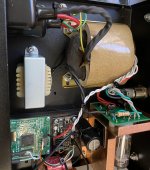
As shown in the attached photo I found of the DAC internals, the power supply is an R-Core transformer fed into a circuit having an EZ80 rectifier and what I think must be a diode rectifier because the tube can be switched in and out of the circuit. The attached photos show the heater and filament supplies (red and grey wires) to the tube rectifier PCB. There are two center tap wires (white wires) from the transformer directly to the ground on the DAC board. The rectifier PCB has a pair of diodes and a pair of resistors at the bottom, a pair of tantalum caps and a third resistor having a stated value of 10k (the bands indicate the actual resistor value is 4.7k 5%) that is maybe for current limiting. The rectified power (black wire) then passes through a choke and then to the DAC board. There is a cap across the V+ and ground at the DAC board inputs.
So this is the total of my knowledge of the power supply. Can anyone help me figure out the rectifier schematic and the proper component values and voltages for the transformer supplies? I am think about just using the EZ80 rectifier without a switch for taking the tube in and out of the circuit.
Thanks in advance.
I am teaching myself some tube knowledge and thought I would start with a clone of the Border Patrol DAC. I know that DAC uses off the shelf XMOS and DAC boards with no output buffer so that portion is simple. The DAC board power supply must be between 11-20V DC.
As shown in the attached photo I found of the DAC internals, the power supply is an R-Core transformer fed into a circuit having an EZ80 rectifier and what I think must be a diode rectifier because the tube can be switched in and out of the circuit. The attached photos show the heater and filament supplies (red and grey wires) to the tube rectifier PCB. There are two center tap wires (white wires) from the transformer directly to the ground on the DAC board. The rectifier PCB has a pair of diodes and a pair of resistors at the bottom, a pair of tantalum caps and a third resistor having a stated value of 10k (the bands indicate the actual resistor value is 4.7k 5%) that is maybe for current limiting. The rectified power (black wire) then passes through a choke and then to the DAC board. There is a cap across the V+ and ground at the DAC board inputs.
So this is the total of my knowledge of the power supply. Can anyone help me figure out the rectifier schematic and the proper component values and voltages for the transformer supplies? I am think about just using the EZ80 rectifier without a switch for taking the tube in and out of the circuit.
Thanks in advance.
Attachments
Last edited:
They WHAT? used a EZ80 for powering a DAC?
I would just build your DAC with a LM317/LT1085 set for 15V output and approx 15VAC rectified in. and call it a day.
I would just build your DAC with a LM317/LT1085 set for 15V output and approx 15VAC rectified in. and call it a day.
v4lve lover, that would defeat the purpose of my project. Thanks though.
Your purpose is unclear.
Are you building from scratch a clone of the DAC in your photo? Is this a stock photo or one taken from an example in your possession? Why did you choose this project to learn about tubes? Why are you trying to clone something without a schematic, if that is what you are planning.
Perhaps you could receive more help if you provide context to this project.
Why do you prefer tube rectification over solid state?
What is the current demand of this circuit?
Does the circuit require a high impedance power supply that the tube circuitry provides?
What is the current demand of this circuit?
Does the circuit require a high impedance power supply that the tube circuitry provides?
Download PSUD2 if you really want to use a tube rectifier for this project. Usually the opamps after a DAC would be run from a dual supply . So it's unclear if the device in question uses a single supply or "splits the rail" with something like a TLE2426 to get a midpoint.
My advice is pick a more conventional design not based around a gimmick.
My advice is pick a more conventional design not based around a gimmick.
I am simply trying to clone the Border Patrol DAC which uses commercially available XMOS and DAC boards and a EZ80 rectified power supply. And I see this as an opportunity to learn a bit about tube electronics. That is my purpose.
As for schematics, you can see in the photo that the DAC is simply an assembly of commercially available XMOS and DAC boards. We do not need a schematic for those portions.
The XMOS is here: 384kHz Asynchronous USB to I2S/SPDIF CM6631A PCB - DIYINHK
The DAC is here: DAC-NOS1 - SELLARZ
Obviously, I could also just grab a commercially available power supply from either of the above vendors, add a transformer, and slap it all together. But the many glowing reviews of the BP DAC state that the tube rectification adds some voodoo magic to the sound so I want to stick with trying an EZ80 rectified power supply.
So any help I could get from the tube gurus here in figuring out the power supply would be greatly appreciated!
Hi Dualuxe,
Welcome to the world of "high end" nonsense. But, this is as good a project as any to learn about tube rectification. The tube rectifier isn't well suited to this use, but what the heck? astoffer gave you excellent advice ...
Don't ask us for this information, this is how you learn. Good luck with your project
-Chris
Welcome to the world of "high end" nonsense. But, this is as good a project as any to learn about tube rectification. The tube rectifier isn't well suited to this use, but what the heck? astoffer gave you excellent advice ...
Do exactly that. It allows you to play "What if?" and get a feel for how the tube will react. The transformer is part of the picture too. Keep an eye on the reality of tubes though. You need to figure out how much current ad voltage you need, and also if and how much a change there is between minimum and maximum current draw.Download PSUD2 if you really want to use a tube rectifier for this project.
Don't ask us for this information, this is how you learn. Good luck with your project
-Chris
And I see this as an opportunity to learn a bit about tube electronics. That is my purpose.
Unregulated tube rectifier circuits are really simple. A few minutes of online searching will bring up schematics that will answer your questions.
But the many glowing reviews of the BP DAC state that the tube rectification adds some voodoo magic to the sound so I want to stick with trying an EZ80 rectified power supply.
One person's voodoo is another person's nonsense.
So any help I could get from the tube gurus here in figuring out the power supply would be greatly appreciated!
You've been asked questions and received comments already that point to the pros and cons of tube rectifiers, particularly for this application. However, I understand where you are coming from; I have built a number of tube guitar amps with various features other builders didn't find important to them, and those projects were worthy learning experiences. You just need to put in some personal research first since you will be better served by learning about tube rectification circuits rather than having someone here do it for you, since they are very simple. One big advantage for you is you already know the tube that was used - EZ80. That tells you the voltage drop and current capacity the designer used for your circuit. I previously asked about the current draw - you will need that for the transformer selection. Definitely do what astouffer and anatech advised and download PSUD2. Also, start doing some reading about tube operation and circuits, not just rectification.
I am simply trying to clone the Border Patrol DAC which uses commercially available XMOS and DAC boards and a EZ80 rectified power supply. And I see this as an opportunity to learn a bit about tube electronics. That is my purpose.
As for schematics, you can see in the photo that the DAC is simply an assembly of commercially available XMOS and DAC boards. We do not need a schematic for those portions.
Sounds like you would like to build an EZ80 rectified power supply to power an output stage of the DAC. Is that correct?
What can you tell about this output/buffer stage? What tubes used? Do you have transformer or are you planning to buy buy one?
There is no buffer stage in this thing. Just the TDA1543 capacitor-coupled to the output connectors.What can you tell about this output/buffer stage? What tubes used? Do you have transformer or are you planning to buy buy one?
The PSU seems to be full-wave center-tapped rectifier, switchable between the EZ80 and SS diodes (with RC snubbers and voltage-dropping resisor), with choke input filter. The funny thing is the voltage is then fed to the 78M08 regulator on the DAC board.
Hi Dualuxe,
Welcome to the world of "high end" nonsense.
-Chris
My thoughts exactly Chris. 😉
The PSU seems to be full-wave center-tapped rectifier, switchable between the EZ80 and SS diodes (with RC snubbers and voltage-dropping resistor), with choke input filter. The funny thing is the voltage is then fed to the 78M08 regulator on the DAC board.
TG, this is exactly the information I am seeking. Thank you.
Schematics of a typical EZ80 rectifier circuit are readily available online, but the use of RC snubbers in that circuit is not. Would these be in series on each filament leg? And is the voltage dropping resistor in series between the B+ pin and the choke?
Using tube rectifier for 12V or so is a stupid gimmick , I would not trust those designers for any real good performance from that DAC 😀
Most likely they are parallel to the SS diodes.Schematics of a typical EZ80 rectifier circuit are readily available online, but the use of RC snubbers in that circuit is not. Would these be in series on each filament leg?
Hard to tell from the photo, but I'd suggest it is used in series with SS rectifer to mimic the behaviour of the EZ80 (vacuum rectifiers have much bigger voltage drop than SS ones).And is the voltage dropping resistor in series between the B+ pin and the choke?
It is indeed. But it's quite coherent with the rest of the design 😀Using tube rectifier for 12V or so is a stupid gimmick
Sigh! OP, what is your goal?
Trying to power a 12 Vdc circuit with an EZ80 tube rectifier? I thought we established that you want to power a tube output stage for the DAC.
Please be explicit, and help will come.
Trying to power a 12 Vdc circuit with an EZ80 tube rectifier? I thought we established that you want to power a tube output stage for the DAC.
Please be explicit, and help will come.
I think this is an excellent example of someone wanting help but NOT knowing what to ask.
Folks, what can we do to help people without much tube knowledge to ask the right questions and get the right help? It is important NOT to loose people like that. So, what do we do?
OP, you asked good questions; we just did not know how to respond.
Folks, what can we do to help people without much tube knowledge to ask the right questions and get the right help? It is important NOT to loose people like that. So, what do we do?
OP, you asked good questions; we just did not know how to respond.
I think, that this design uses a 10K in series with each plate of the EZ80. That way you Could swamp the internal resistance of the EZ80 and make sure that the tube to tube variation found in the EZ80 wont affect the final DC voltage too much.. But this is just a wild guess from the scarce information OP provided. If i had to design it, id put some UF4007 in each anode leg too so an internal short doesnt take out anything.
Copying the board 1:1 with that EZ80 is doable in around 45 minutes if you know your way around Eagle. However i see the tube rectification here as just a gimmick. Any serious designer would either use something allong the lines of 1N5820 or UF4003 for rectification. Cause this is just a very expensive space heater with a tube to look cool.
Copying the board 1:1 with that EZ80 is doable in around 45 minutes if you know your way around Eagle. However i see the tube rectification here as just a gimmick. Any serious designer would either use something allong the lines of 1N5820 or UF4003 for rectification. Cause this is just a very expensive space heater with a tube to look cool.
- Home
- Amplifiers
- Tubes / Valves
- Need Help With EZ80 Rectifier