The hostility to my question here is really bothersome. I have been on this forum for years and never had any issues. My original post asks "Can anyone help me figure out the rectifier schematic and the proper component values and voltages for the transformer supplies?" Why has this become so difficult?
Please don't feel offended, @dualuxe, we are asking because we are eager to help and want to understand the original question, which still needs context.
Let me ask:
Is this something you have in your possession? I.e. have you bought the parts and want to put it together now? In that case, please tell us what you have.
If not, why do you want to buy this and not something else that has better documentation?
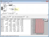
According to PSUD2 simulation, a good starting point would be a standard 48+48V transformer. The choke on post #1 seems to be 5H and the capacitor 2200uF. With 90mA load, the output would be 14V, a good choice for the following UA7808. Max input voltage for UA78xx regulators is 35V, this means that load current should never drop below 20mA if the choke DCR is 30 ohm. A test with a dummy load is required to avoid costly overvoltages at the regulator input. If the load is significantly less than 90mA, a 36+36V or 24+24V transformer would be a better choice. It is not possible to guess the connection of the 10K resistor and capacitors on the picture, but they are probabily used with the silicon rectifier. It is trivial to build a quick prototype and check if this unique circuit does indeed make a sonic difference compared to a standard solid state rectifier. My starting guess is that the sonic signature of the DAC comes from something else; even a tiny deviation from the standard such as a changed resistor or capacitor value may make a difference but it may be a less convincing value proposition for some prospect customers.
Attachments
Exactly what I was hoping for pcan and thanks for all the other responses. I have confirmed that the DAC board requires 60mA and the XMOS board must need about the same. So with a total draw of about 120mA, what needs to change (if anything) in the values pcan has calculated?
i would use a shunt made out of TL431 and a PNP transistor. thats really low noise and simple..
You could also build the regulator itself out of a LM317 and a 6C19 and leave the rectification itself to solid state diodes
You could also build the regulator itself out of a LM317 and a 6C19 and leave the rectification itself to solid state diodes
What the heck? It will output voltage and burn out faster, but it will work in a fashion. It seems that this project is being pushed through no matter what the tube specs are, so it's all in the wind.
dualuxe, I wish you would have listened to some very learned people here. Your project is demanding more current than the tube is rated for, but on and on you go.
Use PSUDII to figure out your supply voltage requirements and at least approach it with some idea of what to expect and what you need for a transformer. Just because someone did it, doesn't mean they did it properly (they didn't).
-Chris
Dualuxe, the short answer to your question would be to input 120mA in the PSUD simulation instead of 90mA. The output voltage with a 55V transformer would be 13V, enough for your purpose. Unfortunately, expecially on a unconventional circuit like this one, the simulation only bring us approximate component values, some tests are needed to get exact values and to discover potential pitfalls. As example: are we sure about the 120mA total draw? I suspect that if this value is correct, they would have fitted a EZ81 instead of the EZ80. But: 120mA is only 30% more than the EZ80 datasheet maximum value so I guess that the tube will survive the warranty period anyway at 120mA. It would be wise to add a 5W 30V protection zener after the choke: if the digital board enters a shutdown state, the current draw will become negligible and the voltage after the choke will get over 50V, damaging the digital board voltage regulator.
Let's be serious ... if you look at the picture there are 2 cheap boards screw in with poor soldered wires between them , an amateur job . Even that TO220 regulator is not supposed to be there , is just added by someone .
There is a CI with heatsink , probably the DAC itself ... at 3,3V how much current do you think would consume to heat up ? 40mA 😛 Even the LED on the board would draw 5mA for nothing .
The vacuum tube rectifier is the last concern when you look at that job .
If we talk in general , this stuff like DACs , decoders , digital stuff , would consume plenty of current in spikes even if the average is much lower . So you wouldn't want a power supply with high internal resistance like a tube to sag when more current is needed . But even the idea of using a vacuum tube for this is crazy
Last edited:
Hi Eli,
Yes, very true. Choke input filter with a bleeder might help the voltage bounce issue with a variable load current.
Its just not pretty. Wrong part for the job at hand.
-Chris
Yes, very true. Choke input filter with a bleeder might help the voltage bounce issue with a variable load current.
Its just not pretty. Wrong part for the job at hand.
-Chris
According to PSUD2 simulation, a good starting point would be a standard 48+48V transformer. The choke on post #1 seems to be 5H and the capacitor 2200uF. With 90mA load, the output would be 14V, a good choice for the following UA7808. Max input voltage for UA78xx regulators is 35V, this means that load current should never drop below 20mA if the choke DCR is 30 ohm. A test with a dummy load is required to avoid costly overvoltages at the regulator input. If the load is significantly less than 90mA, a 36+36V or 24+24V transformer would be a better choice. It is not possible to guess the connection of the 10K resistor and capacitors on the picture, but they are probabily used with the silicon rectifier. It is trivial to build a quick prototype and check if this unique circuit does indeed make a sonic difference compared to a standard solid state rectifier. My starting guess is that the sonic signature of the DAC comes from something else; even a tiny deviation from the standard such as a changed resistor or capacitor value may make a difference but it may be a less convincing value proposition for some prospect customers.
Pcan, in your screen shot is the 6 ohm resistor on the CT an internal value or is it an actual resistor? Thanks.
The 6 ohm value is the resistence of the transformer winding. A wild guess, it should be measured on the actual transformer. I suggest to get a transformer with dual primary windings (117+117) and connect them in parallel to the 117v mains. This way, if the actual current draw is lower than expected and the output voltage is too high, it would be possible to rearrange the primary windings in series and maybe add a filter capacitor before the choke to get a lower voltage. This is not possible with 230/240V mains.
Hi - this is an old thread but I wondered if you ever resolved the design and made a clone to listen to in the end? I am thinking of attempting the same.Pcan, in your screen shot is the 6 ohm resistor on the CT an internal value or is it an actual resistor? Thanks.
Thanks
- Home
- Amplifiers
- Tubes / Valves
- Need Help With EZ80 Rectifier