 Hi All,
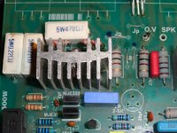
I have a few of these Blazer PCB, s that had the trimmers replaced, one turn with multi turn. Not sure if they are correct.
Board has a 2-5K. Two have 5k and two have 10k. Will post pics. Feel free to comment on anything that may need upgraded or...
AND, how and why to adjust this single trimmer? For crossover point or BIAS?
Thanks
P.S.
Not sure if it is 500w.
Attachments

"Not sure if it is 500w"
With ±57V it would make a nice 120W/8Ω amplifier, would need more outputs to drive 4Ω.
The whole thing looks a bit scary to me.
With ±57V it would make a nice 120W/8Ω amplifier, would need more outputs to drive 4Ω.
The whole thing looks a bit scary to me.
Last edited:
Thanks for taking the time to reply.
Thanks so much for answering my cry for help. Let me give some background info.
When I lived in Texas, a friend of mine gave me six of these boards and enough Sankens, 3858s and 1494s, to populate two boards. He was using 10 with no problems.
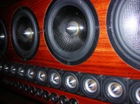
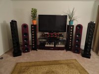
I was using two to drive my 3-way line arrays that would dip down to 2ohms at certain frequencies with no problems. They are, were, apx 7 foot, 250lbs each done in African Bubinga. They loved lots of power, clean power, and the Blazer boards delivered it quite well.
I moved, three times, and the line arrays were damaged while in storage and the amp needed cleaning from the road construction next to the storage. I shorted out an output transistor while taking readings on the amp. I ordered new Sankens, REAL ONES, some WIMA MKP4s to upgrade the coupling caps and new driver transistors (C2037s & A940s). full. I’m assuming these are the driver tranies and since they share the same trimmer pot, that this pot sets the crossover point for the N & P output transistors. I don’t build enough amplifiers to fully understand the transistor circuits.
Thanks so much for answering my cry for help. Let me give some background info.
When I lived in Texas, a friend of mine gave me six of these boards and enough Sankens, 3858s and 1494s, to populate two boards. He was using 10 with no problems.
I was using two to drive my 3-way line arrays that would dip down to 2ohms at certain frequencies with no problems. They are, were, apx 7 foot, 250lbs each done in African Bubinga. They loved lots of power, clean power, and the Blazer boards delivered it quite well.
I moved, three times, and the line arrays were damaged while in storage and the amp needed cleaning from the road construction next to the storage. I shorted out an output transistor while taking readings on the amp. I ordered new Sankens, REAL ONES, some WIMA MKP4s to upgrade the coupling caps and new driver transistors (C2037s & A940s). full. I’m assuming these are the driver tranies and since they share the same trimmer pot, that this pot sets the crossover point for the N & P output transistors. I don’t build enough amplifiers to fully understand the transistor circuits.
Attachments
"I was using two to drive my 3-way line arrays that would dip down to 2ohms at certain frequencies with no problems. "
At ±70V, I don't buy it. I might try it with six~eight pairs per channel.
At ±70V, I don't buy it. I might try it with six~eight pairs per channel.
So what is the trimmer for
Glad you understand the circuit.
So, what is the trimmer value and how to adjust it?😕
Thanks
Glad you understand the circuit.
So, what is the trimmer value and how to adjust it?😕
Thanks
Hello Paul, I would stay with 5k ohm trimpots, 10 turn is fine.
Connect a 100W incandescent lamp in series with your 110V supply, one module only powered.
Connect voltmeter across one of the 0.22 ohm 5W emitter resistors, soldered connection is best when measuring low voltages.
Adjust trimpot for 10mV across emitter resistor....= 45mA bias current.
Check DC offset and if ok, remove lamp and connect 110V power directly.
Monitor 10mV whilst allowing amp to thermally stabilise.
If required, adjust trimpot.
This setting gives 45mA bias current which may not be optimal...increasing bias current may reduce distortion slightly, at the expense of greater heat generation and static power consumption.
See how you go.
Dan.
Last edited:
Thanks so much for answering my cry for help. Let me give some background info.
When I lived in Texas, a friend of mine gave me six of these boards and enough Sankens, 3858s and 1494s, to populate two boards. He was using 10 with no problems.
I was using two to drive my 3-way line arrays that would dip down to 2ohms at certain frequencies with no problems. They are, were, apx 7 foot, 250lbs each done in African Bubinga. They loved lots of power, clean power, and the Blazer boards delivered it quite well.
I moved, three times, and the line arrays were damaged while in storage and the amp needed cleaning from the road construction next to the storage. I shorted out an output transistor while taking readings on the amp. I ordered new Sankens, REAL ONES, some WIMA MKP4s to upgrade the coupling caps and new driver transistors (C2037s & A940s). full. I’m assuming these are the driver tranies and since they share the same trimmer pot, that this pot sets the crossover point for the N & P output transistors. I don’t build enough amplifiers to fully understand the transistor circuits.
I think using 5k ohm trimpots will be fine, you can use one capasitor input with double of uF (it will be +/- 1uF), for final transistor it will be more suitable if using same LOT code of transistor with complement. This amp low watt but fair sound.
For seting trimpots agree with mr. Max Headroom. 🙂
Glad you understand the circuit.
So, what is the trimmer value and how to adjust it?😕
Thanks
other way to adjust it 😉 :
Attachments

Yess indonesian product so verry familiary...... Xixixixiii bad english brow naff..... Next be oK...
actually very familiar and famous PA in Indonesia...i was try and successfully modified by TEF,QC and EF or CF mode this amplifier (i used 20A and 55VAC-CT)...but for more application you can read in amplimos amplifier mode...there you can find each stage explanation. So...if you made this amp by default mode...actually only unstable output power where this amp drive loud (IDN: suarane kenceng tapi gak padat...may you can translate this words hehehehe...).
Mr. Paul...this trimmer you can search by google : keyword= bias adjuster schematic, 'cos this schematic some part were wrong position...this timer used to change bias, may you can modified by change some value of R and C also Q should be placed on HS to stabilized bias.
Mr. Paul...this trimmer you can search by google : keyword= bias adjuster schematic, 'cos this schematic some part were wrong position...this timer used to change bias, may you can modified by change some value of R and C also Q should be placed on HS to stabilized bias.
Last edited:
Hi Paul, ...Thanks so much for answering my cry for help. Let me give some background info.
When I lived in Texas, a friend of mine gave me six of these boards and enough Sankens, 3858s and 1494s, to populate two boards. He was using 10 with no problems.
....
I don’t build enough amplifiers to fully understand the transistor circuits.
at what voltage & load do you use for this amp?
More info for more suggestion
from Mr Indra because he can help you how to maximize the blazer 🙂
I'm not so familiar with blazer, but I've build one too
(@ Mr. Indra, Naf, Savero, Risqi, ikut absen 😀)
View attachment 365959Hi All,
I have a few of these Blazer PCB, s that had the trimmers replaced, one turn with multi turn. Not sure if they are correct.
Board has a 2-5K. Two have 5k and two have 10k. Will post pics. Feel free to comment on anything that may need upgraded or...
AND, how and why to adjust this single trimmer? For crossover point or BIAS?
Thanks
P.S.
Not sure if it is 500w.
Hi, where you get the schematic? Are you sure that it is correct?
THANKS for the input
Indonesian, yes BGR Blazer BOARD. He sold on e bay and had a web site. Let me look at these to night and get an answer. I will look at the schematic and break it down if I can.
Thanks
Again
Indonesian, yes BGR Blazer BOARD. He sold on e bay and had a web site. Let me look at these to night and get an answer. I will look at the schematic and break it down if I can.
Thanks
Again
Indonesian, yes BGR Blazer BOARD. He sold on e bay and had a web site. Let me look at these to night and get an answer. I will look at the schematic and break it down if I can.
Thanks
Again
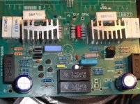
this is bottom view, maybe can help

Attachments
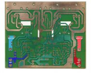
Good info, thanks. And PICs
Interesting, you have +/-55/110v. This can take up to 110v as designed?
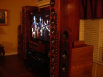
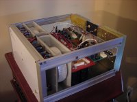
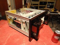
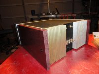
I was trying to find boards (seperate for each chanel) to fit my enclosure and power supply. I have apx +/- 64 volt rails. Two 45-0-45 600va Torids, 16X 10,000uf Panasonic 100v caps (pic enclosed) plenty of filtering, soft start, speaker protection, wood enclosure of African Wega front and Purple Hart sides.
I designed it for high powered boards with the Sankens. There is some Aussy amps, HX-200 using same amount of transistors with 200-330watts I was thinking about replacing the Blazers with. BUT, these are MOSFETS and as I understand it, BJT like the Sankens deliver more power, acording to Elliot on ESP. I have 2 of his project 101 mosfet boards I am building also. Plus 3xPA150 using LM3886 chips, and the F5 Clone boards I have not started yet.
So, I would like to stick with the BJT in this amp to power up anything. My KT88 60per sounds good also (PIC attached). I would like to here the diffrence in each one. The KT88 is the only one I have working now, HA!
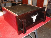
All the info is great!! I hope you like the PICs. Have a few more. And if someone needs info on wood or finishing...just ask.
Paul
this is bottom view, maybe can help
Interesting, you have +/-55/110v. This can take up to 110v as designed?
I was trying to find boards (seperate for each chanel) to fit my enclosure and power supply. I have apx +/- 64 volt rails. Two 45-0-45 600va Torids, 16X 10,000uf Panasonic 100v caps (pic enclosed) plenty of filtering, soft start, speaker protection, wood enclosure of African Wega front and Purple Hart sides.
I designed it for high powered boards with the Sankens. There is some Aussy amps, HX-200 using same amount of transistors with 200-330watts I was thinking about replacing the Blazers with. BUT, these are MOSFETS and as I understand it, BJT like the Sankens deliver more power, acording to Elliot on ESP. I have 2 of his project 101 mosfet boards I am building also. Plus 3xPA150 using LM3886 chips, and the F5 Clone boards I have not started yet.
So, I would like to stick with the BJT in this amp to power up anything. My KT88 60per sounds good also (PIC attached). I would like to here the diffrence in each one. The KT88 is the only one I have working now, HA!
All the info is great!! I hope you like the PICs. Have a few more. And if someone needs info on wood or finishing...just ask.
Paul
Attachments
- Home
- Amplifiers
- Solid State
- Need help with BLAZER 500w PCB