Hey all,
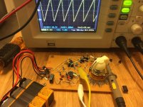
I'm cobbling together a type of curve tracer to test small (~10mA) JFET constant current sources, but I'm seeing what I think is an artifact with the shunt signal amplifier.
The basic idea is to create a voltage supply which varies over a small window (e.g. 10V +/- 0.5V at 1kHz), apply the voltage to the CCS followed by a shunt resistor, then look at the shunt resistor's voltage signal on a scope to see how well the CCS is performing. My initial work on this is detailed here: https://www.diyaudio.com/forums/sol...ed-data-j105-nchannel-jfet-3.html#post6401985
This worked, but the shunt signal was too small, so I added an amplifier to the shunt signal.
The problem is, I am seeing what I think is an artifact, and I'm not sure where it is coming from, so I thought I would turn to the forum for help.
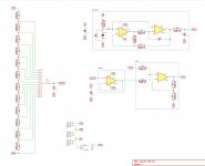
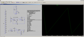
First, here's the sawtooth-like generator circuit:
I'm cobbling together a type of curve tracer to test small (~10mA) JFET constant current sources, but I'm seeing what I think is an artifact with the shunt signal amplifier.
The basic idea is to create a voltage supply which varies over a small window (e.g. 10V +/- 0.5V at 1kHz), apply the voltage to the CCS followed by a shunt resistor, then look at the shunt resistor's voltage signal on a scope to see how well the CCS is performing. My initial work on this is detailed here: https://www.diyaudio.com/forums/sol...ed-data-j105-nchannel-jfet-3.html#post6401985
This worked, but the shunt signal was too small, so I added an amplifier to the shunt signal.
The problem is, I am seeing what I think is an artifact, and I'm not sure where it is coming from, so I thought I would turn to the forum for help.
First, here's the sawtooth-like generator circuit:
Attachments
Last edited:
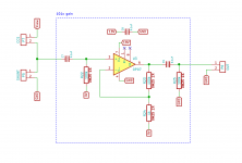
I then added an amplifier to the shunt signal:
Initially I used 101x gain, but when I noticed the problem, I also tried lowering the gain to about 10x (bodged a 10k in parallel with the 100k), but that wasn't a solution.
To clear up any possibility that this was a problem with the JFET CCS, I replaced that with a simple resistor.
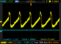
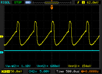
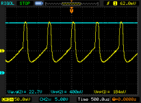
I tried a few values of shunt resistors and found the problem only exists when the shunt / signal is below a certain level.
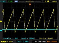
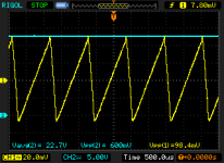
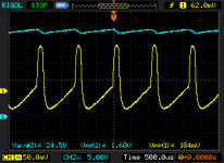
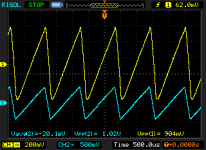
First, here is a 100k resistor as a stand-in for the CCS, with a 1k shunt, tested with about 1.1V +/- 0.5V, and with 22.7V +/- 0.5V (ignore the inaccurate 600mV p-p readout).
No problems so far.
Edit: note these shots are with the feedback resistor bodge for a gain of 10x, not 101x.
Initially I used 101x gain, but when I noticed the problem, I also tried lowering the gain to about 10x (bodged a 10k in parallel with the 100k), but that wasn't a solution.
To clear up any possibility that this was a problem with the JFET CCS, I replaced that with a simple resistor.
I tried a few values of shunt resistors and found the problem only exists when the shunt / signal is below a certain level.
First, here is a 100k resistor as a stand-in for the CCS, with a 1k shunt, tested with about 1.1V +/- 0.5V, and with 22.7V +/- 0.5V (ignore the inaccurate 600mV p-p readout).
No problems so far.
Edit: note these shots are with the feedback resistor bodge for a gain of 10x, not 101x.
Attachments

Can you point to the artifact that you're seeing? What's the significance of the blue/cyan trace on the scope?
BTW, the humble LM555 timer IC can make something that resembles a sawtooth as well. If you set the IC up to be an astable multivibrator, you'll find a "sawtooth" on pin 6 (threshold).
Tom
BTW, the humble LM555 timer IC can make something that resembles a sawtooth as well. If you set the IC up to be an astable multivibrator, you'll find a "sawtooth" on pin 6 (threshold).
Tom
I guess our posts crossed. Now let me mull over the cause of that hump...
Would you be able to add the bits connected to CCS and SHUNT to the schematic?
Tom
Would you be able to add the bits connected to CCS and SHUNT to the schematic?
Tom
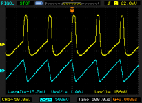
Thanks tomchr, oops, actually I thought the blue trace was the input signal to the DUT, but actually it was the DC offset input to the sum circuit, so it was just 22.7V without the +/- 0.5V added.
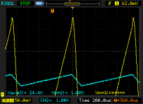
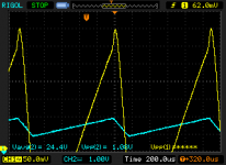
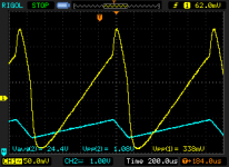
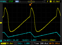
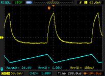
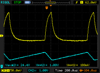
Here are two new scope shots, where the blue is actually the DUT input signal, both DC and AC coupled.
Here are two new scope shots, where the blue is actually the DUT input signal, both DC and AC coupled.
Attachments

tomchr, this schematic should be what I'm actually testing right now.
There was a mistake in what I posed earlier, I showed Vsaw going directly into the DUT, which is incorrect. Vsaw goes to the summing amp, and the output of the summing amp goes into the DUT.
There was a mistake in what I posed earlier, I showed Vsaw going directly into the DUT, which is incorrect. Vsaw goes to the summing amp, and the output of the summing amp goes into the DUT.
Attachments
Last edited:
I should also mention that I've tried both an OP07 and a ua741 as the final amplifier op amp. Same results.
The other two op amps are LM358's.
I've also tried both ceramic and film caps on the input and output of the amplifier op amp. No difference.
The other two op amps are LM358's.
I've also tried both ceramic and film caps on the input and output of the amplifier op amp. No difference.
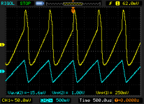
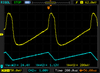
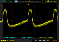
Here's a different look: shunts of 100R, 150R, 220R, 330R, 470R, 680R, 1k, but all with the same vertical scale, and with the peak of the bump at the same division.
edit: I wonder if this is inductive in nature?
edit: I wonder if this is inductive in nature?
Attachments
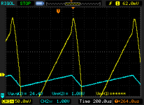
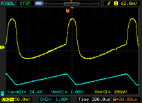
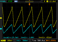
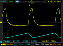
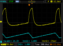
So this is interesting. Here are shunts of 100R, 47R, 10R, 4.7R, 1R and "0R" (a zero-ohm resistor, actually about 25mR).
So this is unrelated to the signal on the shunt. Perhaps this is just a sloppy ground?
So this is unrelated to the signal on the shunt. Perhaps this is just a sloppy ground?
Attachments


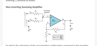
I think the issue is that your summing stage is not a summing stage.
Have a look here: https://www.electronics-tutorials.ws/opamp/opamp_4.html
You'll note that if all the resistors in the summing amp are equal, you'll get -(V1+V2+V3+...). You'll need an inverting amp stage to get rid of the minus sign (assuming you care about it or can't get rid of it elsewhere in your circuit, that is. You could always just invert the scope input. Personally, I'd just add the inverting gain stage.
I would probably use more modern opamps. OPA2134, NE5532, TL072, etc. would probably work well. Or something even newer. Some of the older opamps can be pretty quirky.
Tom
Last edited:
Possibly slew limiting due to limited power bandwidth in the op-amps you are using? The higher shunt resistances require the op-amp to deliver less current.
What about output capacitor reactance relative to shunt resistance?
What about output capacitor reactance relative to shunt resistance?
tomchr, actually that's the same page I started from, ha! if you scroll down further, you'll see the "non-inverting" version of the circuit which I used.
edit: here's the ltspice file from earlier in the design process.
edit: here's the ltspice file from earlier in the design process.
Attachments
Last edited:
Your issue is one of fundamental functionality, not grounding, capacitor dielectric, etc.
Your "DUT" is just a voltage divider right now, so the circuit should work.
I would test it in blocks. Measure the two inputs to the summing block. Verify that you get the correct output. Measure the "DUT" voltage (pin 1 of the shunt, for example).
I bet one of your opamp stages is cranky. Possibly because you're violating its input voltage specs. The old opamps are not all rail-to-rail I/O.
Tom
Your LTSpice sim spec'd LM324, while the earlier tests showed using an LM358. The latter has an unusual, asymmetrical-drive output stage. Plenty of opamps from that era have trouble driving loads below about 2k ohms. Its internal bias stages lose their minds when too much current is asked of the output.
If I understand correctly what you're trying to do, how about flipping the sawtooth (abrupt rise, then gradual ramp down), feeding it to the inverting input (of the DUT driver amp, wired for gain of -1)), then bias the '+' input with the variable voltage from the 12 position switch. Then you could even skip the selector switch buffer amp! It would also eliminate the need for any arithmetic to predict the drive waveform.
But you probably do need a more *modern* opamp. Probably an output buffer, too.
Also, the J105 is only rated 25V -- a high-current spike is probably going to occur Somewhere within a 0 to 27V range.😉
Cheers
- Home
- Design & Build
- Equipment & Tools
- Need help with baby's first curve tracer