I would assume that they are good. I only got them a week ago and only applied power to them for the tests that you have asked for. Perhaps they are the wrong spec IRFZ44s? Here is a link to the data sheet for them. http://www.parts-express.com/pdf/irfz44npbf.pdf
Remove them and check them out of the circuit. If you don't know how to check them, follow the link in the sig file below.
OK...I tested both according to your web page "Basic Transistor Testing" and found that one was bad and the other was fine. I will order 2 more just so I have a spare. I started to order 3 at first so that I would have a spare and now wish that I had. Oh well. I should have the new ones here in about a week.
Once again....Thanks for the help.
Once again....Thanks for the help.
Order more than 2. I'd suggest that you order 10.
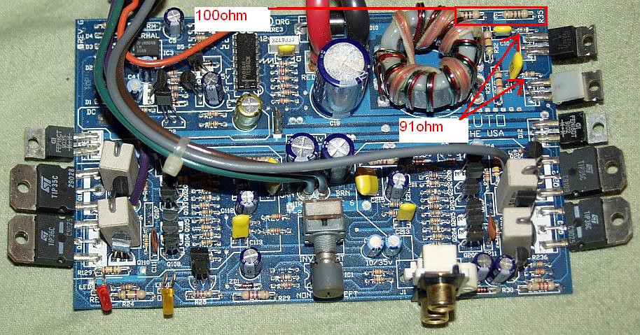
Are the two resistors on the end of the board (R35 and the one next to it) within tolerance?
Do you read 0 ohms between one end of each resistor and the gate pad for one of the power supply FETs?
Are the two resistors on the end of the board (R35 and the one next to it) within tolerance?
Do you read 0 ohms between one end of each resistor and the gate pad for one of the power supply FETs?
Both resistors (R35 and the one next to it, R34) are within tolerance. Brown, black, brown, gold are the bands. 100ohm@5%. The resistors next to the gate pad are the ones that the trace lead to. This trace is good on both as are the resistors.
When you reinstall the FETs, confirm that you read 191 ohms from the gate leg of the FET (red probe directly on the leg of each FET near the FET body) to ground (black probe on ground).
Clamp everything down before applying power.
Clamp everything down before applying power.
I just did a quick check from the pad for leg1 of each FET to ground and found 188.5ohm for each. Also checked the leg3 pad of each FET to ground and got 0 ohms. I will recheck after the IRFZ44's get here and are installed.
Life tends to be a pain sometimes and right now, it is preventing me from working on the amp. I will post again here when I get the FETs installed. Should be a week or so.
Well....a "week or so" has turned into about 2 months. Now that all the Birthday,Thanksgiving, Xmas and New years crap is out of the way, I can get back to it. I have the IFRZ44s and just need to install them. Maybe later today or tomorrow.
Finally got to replace the IRFZ44s. Did a quick power up and the power supply still reads zero volts when the amp is attached. Also, I noticed that the FETs got hot only after a few seconds of power being applied. (this would be because I forgot to mount them on the heat sink) Measuring the pins on the FETs after power up I get
On the one closest to the corner....
Pin 1-2) - 0.0 ohm though, the reading climbs as I hold the probes to the pins
Pin 1-3) - 188.5 ohm
Pin 2-3) - 0.0 ohm though, the reading climbs as I hold the probes to the pins
And on the other one next to the one in the corner....
Pin 1-2) - 0.0 ohm though, the reading climbs as I hold the probes to the pins
Pin 1-3) - 188.5 ohm
Pin 2-3) - 0.0 ohm though, the reading climbs as I hold the probes to the pins
How much current was it drawing?
Are you saying that the voltage on the 12v power supply is draqgged down to 0v when you connect the amp?
If so, does it do this with no remote voltage applied?
Are you saying that the voltage on the 12v power supply is draqgged down to 0v when you connect the amp?
If so, does it do this with no remote voltage applied?
I'm not sure of the amount of current draw as the power supply hasn't a ammeter.
Yes, the the measured output at the terminals when voltage is applied to the amp is zero but, remains at 13.69vdc when the remote turn-on is removed from power.
Yes, the the measured output at the terminals when voltage is applied to the amp is zero but, remains at 13.69vdc when the remote turn-on is removed from power.
Yes, the rectifiers are soldered onto the board. I'm beginning to think that there is something wrong with the remote turn-on circuit.
I removed the rectifiers and the voltage remained at 13.68vdc whether the remote wire was connected or not.
- Status
- Not open for further replies.
- Home
- General Interest
- Car Audio
- Need help w/ old school HiFonics Pluto