It would appear that the outputs are OK. You'll have to replace the power supply FETs before you can determine if there are any other problems. Before applying power, clamp the power supply FETs tightly to the heatsink and insert a 10 amp fuse in the B+ line.
I will order the IRFZ44s today and I should have them and installed in about a week, maybe less. I'll post again when I have them soldered on the PCB.
Thanks again.
Thanks again.
Soldered in the new IRFZ44's as well as the new caps. Put the PCB back into the heatsink and clamped down the FETs. Soldering in the new parts was issue free. No problems and no extra solder. Powered it up and the voltage across the power supply shows 12+ volts and after a couple seconds, drops to approx half. I tried to different power supplies and both did the same.
What direction should I go from here?
What direction should I go from here?
When it attempts to power up, measure the DC voltage from the emitter (leg 3) of the TIP35 (red probe) to the emitter of the TIP36 (black probe) for each channel. Does either go significantly higher than 0.005v?
Is there enamel missing from one of the wires on the transformer (where the wire goes over the top of the core)?
Is there enamel missing from one of the wires on the transformer (where the wire goes over the top of the core)?
Visually inspecting the toroidal transformer, I see no enamel missing.
Upon powering up and measuring from leg 3 of the TIP35 with the red probe to leg 3 of the TIP36 with the black probe produced 0.000 volts after testing multiple times, and also confirming that the VOM was operating properly.
Upon powering up and measuring from leg 3 of the TIP35 with the red probe to leg 3 of the TIP36 with the black probe produced 0.000 volts after testing multiple times, and also confirming that the VOM was operating properly.
Removed both of the rectifiers (FEP16CT & FEN16DT) and the power supply immediately showed 2.3-2.4v. I wavered around in that area and I never got a steady reading.
It's rated at 20 amp. I just checked it with a R/C car battery charger charging a 7.2v battery at 4 amp and it was working fine. I know idle current draw for the Pluto is well under that.
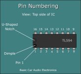
Pull the power supply transistors and post the DC voltage on all 16 pins of the TL494. Place the black meter probe on the amplifier's ground terminal. Place the red meter probe on the point where you need to measure the voltage.
IC#
Pin 1:
Pin 2:
Pin 3:
Pin 4:
Pin 5:
Pin 6:
Pin 7:
Pin 8:
Pin 9:
Pin 10:
Pin 11:
Pin 12:
Pin 13:
Pin 14:
Pin 15:
Pin 16:
IC#
Pin 1:
Pin 2:
Pin 3:
Pin 4:
Pin 5:
Pin 6:
Pin 7:
Pin 8:
Pin 9:
Pin 10:
Pin 11:
Pin 12:
Pin 13:
Pin 14:
Pin 15:
Pin 16:
Attachments
You are referring to the IRFZ44s, correct? I know it's a stupid question but I just wanted to confirm. Also, do I need to put the rectifiers back in?
Ok...got it.
Pin 1: .06
Pin 2: 4.54
Pin 3: .06
Pin 4: .01
Pin 5: 1.51
Pin 6: 3.54
Pin 7: 0.00
Pin 8: 13.68
Pin 9: 5.12
Pin 10: 5.13
Pin 11: 13.68
Pin 12: 13.23
Pin 13: 4.99
Pin 14: 4.98
Pin 15: 4.98
Pin 16: .03
Pin 1: .06
Pin 2: 4.54
Pin 3: .06
Pin 4: .01
Pin 5: 1.51
Pin 6: 3.54
Pin 7: 0.00
Pin 8: 13.68
Pin 9: 5.12
Pin 10: 5.13
Pin 11: 13.68
Pin 12: 13.23
Pin 13: 4.99
Pin 14: 4.98
Pin 15: 4.98
Pin 16: .03
That looks OK.
Was the voltage dragged down (FETs in the circuit) if the remote voltage was not applied?
Was the voltage dragged down (FETs in the circuit) if the remote voltage was not applied?
I put the IRFZ44s back in as well as the rectifiers. Powered it up with the remote wire connected and the power supply slowly climbed up to approx 2.25v before it mostly settled. Powering up without the remote wire attached produced the same results.
Ok. There seems to be a problem with the FETs or the connection to the gate resistor. Are the solder pads for the FETs in perfect condition?
With the FETs in the circuit, do you read 0 ohms between the gate resistor and the gate leg of the FET?
With the FETs in the circuit, do you read 0 ohms between the gate resistor and the gate leg of the FET?
On the lowest scale (320ohm for the continuity test) both measured 0.3ohm. On the lowest resistance scale (3k ohms) both read 0.001ohms. I measured from both the top (from the FET #1 leg to the wire out of the resistor) and the bottom (from solder pad to solder pad) of the PCB. I also checked traces from legs 2 & 3 on the FET to the nearest component. All measured the same as above. These are also the same ohms readings, on both scales, if I touch the two probes together.
- Status
- Not open for further replies.
- Home
- General Interest
- Car Audio
- Need help w/ old school HiFonics Pluto