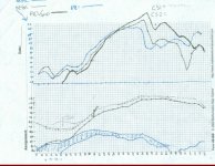
Well thank you for imparting wisdom anyways. here is a scanned pic of the freq response i have taken thus far. the graph on top is taken in the backyard from 3 different angles at about 6 feet away, 2 feet off the floor. the bottom graph is a close mic of the subwoofer and the PR. any dotted lines or shaded areas are measurements with radioshack corrections added. on the top graph there is a major dip in response at about 63hz, like 13db or so of a dip. The close mic of the sub has no such dips. any one able to translate this graph?
Attachments
Here is a simulation of the Parts Express #295-190 in a 120 liter, (4.3 Ft³), box with two Drone Cones tuned to 20 Hz.
The drive voltage is 32 volts, which into 4 ohms is 256 watts-about what a good subwoofer amp puts out.
The lower green line is the whole system output into half space-the way most speaker programs graph it.
The upper green line is the output using average room gain.
The purple line is the speaker's cone excursion at 256 watts.
The red line is the impedance curve. Not how the box tuning is the lowest point between two peakes. That is how it is in a Passive Radiator or vented box.
The simulation program is Subwoofer Simulator by our own member, F4ier. This freeware program simulates many, many curves. These are just a few of them. The file to make room gain shown was done by Serow, another member here.
Pretty good output for a single subwoofer. At 20 Hz, without room gain you are at 108 dB at 256 watts. With room gain you are at 114 dB.
By the way, the MTX 15's you are using as Passive Radiators: What are the model numbers and the Thiele-Small parameters?
Attachments
And here is the output with the Passive Radiators tuned down to 10 Hz.
Upper green line = response with room gain
Lower green = response in half space
Purple = Cone excursion
Red = Impedance
256 Watts power.
As yu can see, bass output goes down slightly.
Upper green line = response with room gain
Lower green = response in half space
Purple = Cone excursion
Red = Impedance
256 Watts power.
As yu can see, bass output goes down slightly.
Attachments
I had to measure the TS parameters myself because i couldn't find them anywhere on the net and the mtx folks weren't too helpful.
Re: 7.1 ohms
Rmax: 29 ohms
Fs: 24.5 hz
Rx: 14.349 ohms
F1: 17 hz
F2: 36 hz
Qms: 2.606
Qes: .8448
Qts: .638032
Cms: .000704207
Vas: 972.42 Liters!
+30 grams Fs2: 20 hz
I took the magnets off the MTX's though, too damn heavy. but i am pretty sure i could put them back in the same spot they were before.
Speekergeek:
Okay, I am just going to punch in the sealed box graph then take a look at things tomorrow.
Here is the graph for a closed box, 120 liters
Upper green line = response in room
Lower green line = response with typical room gain
Red line = impedance
Purple line = cone excursion
As you can see, the sealed box offers slightly less output than either ported box.
Attachments
Speekergeek:
So your output at 30 Hz is about 20 dB down from 63 Hz ?
Was this measured on the ground out in the open, or on the ground against a wall?
One speaker writer simply measured his sub from 4 feet away, with the sub on the driveway against his garage door-which was closed, of course.
Gotta go to bed-catch you tomorrow.
By the way, a quick calculation with Subwoofer simulator says that two Passive Radiators like that require 1.4 kilograms to tune them to 20 hz in a 120 Liter box. That includes the mass on the cone already before adding anything-whic is probably about 125 grams each or 250 grams totoal.
So 1 kilogram total for the two PRs was pretty good bet for this box.
Gotta go. See you tomorrow.
So 1 kilogram total for the two PRs was pretty good bet for this box.
Gotta go. See you tomorrow.
Yeah it appears that way, maybe it is the "PR's" i am using, i saw some stryke audio 15" PR's for 70 bucks, they have the needed excursion (like 30mm), these mtx's probly have like 7mm. Xmas idea for the wifey maybe?
I measured these on the ground about 6 feet from the speaker in an enlosed backyard with no roof, about 9 feet by 17 feet. my sub was on the ground and the spl meter was 2 feet off the ground. tomorrow i will probably drag it out on the front lawn with an extension cord.
I measured these on the ground about 6 feet from the speaker in an enlosed backyard with no roof, about 9 feet by 17 feet. my sub was on the ground and the spl meter was 2 feet off the ground. tomorrow i will probably drag it out on the front lawn with an extension cord.
Since you seem to have some difficulty with the measuring thing, let me make two suggestions.
A) Measure the Thiele-Small parameters of your 15" Dayton DVC.
B) Take out the Passive Radiators, and substitute with two round pieces with holes drilled in them. This will render the box a Closed Box. Since the Closed Box has no variables, you can measure the response of the Closed Box, paying special attention tothe output at 40 Hz, 30 Hz, and 20 Hz.
From the simulations, you can see that a properly tuned Passive Radiator is about 6 dB more putput than the Closed Box at 20 Hz. If you use identical setups for the Closed Box and the Passive Radiators, and you get significantly more output at 20, 30 and 40 Hz than the Closed Box, then you know you are probably correctly tuned, whatever the limitations of your measuring setup.
That is assuming the Thiele-Small specs actually match the published specs to any reasonable degree.
About the Passive Radiator substitute to close off the hole. If you don't have the saws to cut a perfect circle in MDF, try this. Take a piece of ¼" plywood, easily cuttable by a hand held saber saw. Put MTX on the ¼" plywood. Take a pencil and trace around the edges of the MTX. With the saber saw, cut around the inside of the traced line. Place MTX over the newly cut plywood circle, and drill holes into it-now your holes will line up with the box.
Reinforce the ¼" plywood piece with cut 2 by 4's. An inch or so between braces will not harm the stiffness. Simply attach new piece onto the Passive Radiator cutouts, and you now have a Closed box for comparison purposes.
Crudely drawn illustration below shows the idea of what the piece looks like. blue pieces are the 2 by 4's. I would put the side with the braces on on the outside, to avoid problems with whatever rim edge you might have routed into the enclosure. 🙂
Attachments

I seem to be having some trouble with my impedence graph, i think it could be the gear i am using. i have burned test tones onto the cd and am running it off of a compact cd player into my plate amp. out of the plate amp and into the speaker. very many opportunities for flaws there. but it said that fs was 31hz, then i added 30 grams to the cone and the fs didn't change. something is wrong, i may have to wait until i can get better equipment.
Your best bet is to put on the theoretical amount of mass and discard your measurements as inaccurate.
A 30gram change on a 1kg PR is going to be very hard to measure. The frequency change would be sqrt(1.03/1), or about 1.5%, which , if the tuning point is anyhere near to 20Hz, would be 0.3Hz...
If you want to measure the parameters of the woofer and/or the impedance, do it inside and use your computer soundcard and a program such as NCH Tone, http://www.nch.com.au/tonegen/ ,and not a CD.
The proper method is :
http://www.epanorama.net/documents/audio/speaker_parameters.html
or:
http://sound.westhost.com/tsp.htm
Plate amps very frequently have non-flat response, which will wreck havoc with your measurements. USe a receiver instead.
BTW, there is nothing wrong with using old woofers as PR's as long as they have enough excursion. You'll know if they don't have enough because they will start to protest 😉
No Need To Save Up For A Tempest
Apparently Parts Express Tech Service gives better answers if you Email them instead of calling them. If you Email them, maybe they have a chance to actually look something up, instead of just making an educated guess in order to move on to the next phone call.
I sent an Email to Parts Express asking specifically about an extended pole piece. I also pointed out that their Titanic Mark 3 had this extended pole piece, and a symmetrical field as well, as their catalog makes clear-for the Titanic Mark 3.
Check the number on your woofer. It should be the Parts Express #295-190. Is it? Reason I am asking is that some years ago, they sold 15 inch DVC that cost about $80, which I am sure did not have an extended pole piece.
Anyway, I sent an Email to Parts Express Tech department asking about the #295-190, 15" Dual Voice Coil subwoofer and received the following answer from Darren:
I am inclined to believe this, because unlike the tech person I got on the phone call, Darren said unequivocally that it had an extended pole piece. Plus the facts that it seems to be a clone of the Tempest, which has one but doesn't emphasize it in the advertising, and the fact that both Tempest and Parts Express 15" DVC are likely made by Eminence, which seems to favor extended pole pieces over shorting rings in their bass drivers. Even the advertising language of the two seem to be similar.
So it looks like your driver can be used in a Ported or Passive Radiator box. Please let us know that it is in fact the #295-190 which cost around $130, and not the earlier 15" DVC which cost around $80.
Apparently Parts Express Tech Service gives better answers if you Email them instead of calling them. If you Email them, maybe they have a chance to actually look something up, instead of just making an educated guess in order to move on to the next phone call.
I sent an Email to Parts Express asking specifically about an extended pole piece. I also pointed out that their Titanic Mark 3 had this extended pole piece, and a symmetrical field as well, as their catalog makes clear-for the Titanic Mark 3.
Check the number on your woofer. It should be the Parts Express #295-190. Is it? Reason I am asking is that some years ago, they sold 15 inch DVC that cost about $80, which I am sure did not have an extended pole piece.
Anyway, I sent an Email to Parts Express Tech department asking about the #295-190, 15" Dual Voice Coil subwoofer and received the following answer from Darren:
Yes, the #295-190 does have an extended pole piece. This woofer has been tested by several facilities and does have a very linear motor strength vs. excursion. I have seen it used in ported boxes many many times with only positive results.
Best regards,
DarrenK
I am inclined to believe this, because unlike the tech person I got on the phone call, Darren said unequivocally that it had an extended pole piece. Plus the facts that it seems to be a clone of the Tempest, which has one but doesn't emphasize it in the advertising, and the fact that both Tempest and Parts Express 15" DVC are likely made by Eminence, which seems to favor extended pole pieces over shorting rings in their bass drivers. Even the advertising language of the two seem to be similar.
So it looks like your driver can be used in a Ported or Passive Radiator box. Please let us know that it is in fact the #295-190 which cost around $130, and not the earlier 15" DVC which cost around $80.
- Status
- Not open for further replies.
- Home
- Loudspeakers
- Multi-Way
- need help tuning PR's and box! pleeze!