Hi.
I bought some PCB's which are an adaptation of a Marantz MA9S2, but incorporate some custom changes(such as an op-amp-based DC servo), and utilizing multiple pairs ON-Semi 4218A/4302A with 62v rails.
See attached schematic
In testing I'm utilizing an incandescent light bulb in series with the variac, then the transformer, rectifier, caps, then F1A fuses in series with the VCC and VSS rails; milliamp meters in series with each rail, and a voltmeter to probe across each 0.22 emitter resistor to determine the bias current(target is 50mA). Outputs and bias transistor are mounted on large heatsink(Conrad MF35-151.5).
First tests as I slowly bring the rails up to only 1vdc, 2vdc, 3vdc I notice that the rails draw up to almost an amp of current. The voltage across the 0.22ohm emitter resistors reaches about 95 mV(which I calculate as over 400mA bias).
I've checked all my component placement and soldering and it looks fine.
The only changes I made from the stock board were to enlarge the coupling caps slightly, and to locate the VBE multiplier transistor (Q15)on the clamping bar used hold the outputs to the heatink with a 3.5" wiring harness connecting the three transistor leads to the pcb.
I'm afraid to increase the rails any more at this point, until I get some help or advice on what seems to be happening (or is wrong).
I truly appreciate any help at this point!
-Chas
Attachments
Last edited:
Divide and Conquer is the way.
Remove R32 and R33.
Remove R20 and R22.
Ground the base of Q16.
Ground the base of Q19.
Bring up the power supply slowly. If there's still a bunch of current, then you know that the problem lies in something around Q16-Q21.
Good luck...
Akitika GT-101 Audio Power Amplifier Kit
Update My Dynaco
Remove R32 and R33.
Remove R20 and R22.
Ground the base of Q16.
Ground the base of Q19.
Bring up the power supply slowly. If there's still a bunch of current, then you know that the problem lies in something around Q16-Q21.
Good luck...
Akitika GT-101 Audio Power Amplifier Kit
Update My Dynaco
Q16/Q19 bases grounded; 4 resistors removed
Okay.
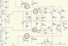
First shown is diagram with referenced resistors circled.
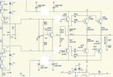
Second is diagram showing removal of said resistors, plus
Q16/Q19 with bases grounded, as recommended.
Test setup will remain the same as before when powering up with variac.
Any other recommended test points for checking this circuit as modified?
-Chas
Okay.
First shown is diagram with referenced resistors circled.
Second is diagram showing removal of said resistors, plus
Q16/Q19 with bases grounded, as recommended.
Test setup will remain the same as before when powering up with variac.
Any other recommended test points for checking this circuit as modified?
-Chas
Attachments
We're in sync. Check voltage on all emitter resistors of output transistors. That lets us know where the high current goes.
Thanks
Thanks.
🙂
I will have to wait until after the work week to proceed further in the testing .
-chas
Thanks.
🙂
I will have to wait until after the work week to proceed further in the testing .
-chas
noticed something weird
Haven't had opportunity to fire up the variac yet (maybe tomorrow), but I decided to measure the power supply leads with an Ohmmeter and found the following anomaly:
On Ch R pcb I measured 100 ohms from Vcc to Gnd, 20 ohms from Vss to Gnd and 20ohms from Vcc to Vss, while on
Ch L pcb I measured 20 ohms from Vcc to Gnd, 100ohms from Vss to Gnd and 20ohms from Vcc to Vss.
Any obvious reason(s) for: 1) the resistances being different for Vcc & Vss, and, 2) difference between the R&L channel boards?
-Chas
Last edited:
Now with bases of Q16, Q19 grounded.
The above resistance measurements were with the specified resistors removed.
The following are with bases grounded on Q16 & Q19:
On Ch R pcb I measured 70 ohms from Vcc to Gnd, 7 ohms from Vss to Gnd and 20ohms from Vcc to Vss, while on
Ch L pcb I measured 7 ohms from Vcc to Gnd, 70 ohms from Vss to Gnd and 20ohms from Vcc to Vss.
Before I fire up to test with the power supply I'd like to hear opinions on possible reasons for the anomalies between channels.
THX
-Chas
Last edited:
The schematic shows a (badly drawn) 1K trimpot next to C12. That's to set the quiescent current. You need to adjust it to get the correct voltage across the 0.22ohm emitter resistors. You'll have to undo all the changes djoffe recommended first though.I notice that the rails draw up to almost an amp of current. The voltage across the 0.22ohm emitter resistors reaches about 95 mV(which I calculate as over 400mA bias).
It's a really bad idea to try to measure resistance in-circuit with power applied. Hopefully the meter's not damaged.I decided to measure the power supply leads with an Ohmmeter.....
.....while on
It's a really bad idea to try to measure resistance in-circuit with power applied. Hopefully the meter's not damaged.
I think you misread my meaning.
No power has been applied while measuring resistances of the unconnected Vcc, Gnd, and Vss wires on the amp board.
The phrase 'while on' in the sentence was ",while on Ch L pcb I measured..."
I could have just as well have written ", and on the...".
Sorry if I confused you.
Ordered another set of PCB's (just for the heck of it). Should arrive soon(?).
In one, will insert only components for driver & output stage, so as to completely isolate sections for measurement. In other will assemble only input stage for same reason. Will compare E/I measurements to my built-up boards.
If anyone else has tried these kits please let me know your results:
MA9 S2 Clone 150W 150W 8ohm Poweramp Kit High End MJL4281A MJL4302A | eBay
-Chas
Hi,
2 of my friends try to build this amp, with many many problems. I don't know what was the problem, but as I remember, there was no success.
This amplifier has NO any relation to Marant MA9. The owner of this design removed all features, what makes MA9 excellent amplifier....
Sajti
2 of my friends try to build this amp, with many many problems. I don't know what was the problem, but as I remember, there was no success.
This amplifier has NO any relation to Marant MA9. The owner of this design removed all features, what makes MA9 excellent amplifier....
Sajti
I have a set running
Hi,
I have a pair of these with the MJL4281A + MJL4302A running on 63v rails as my garage workshop amp, I think from that vendor. I just assembled them and fired them up carefully with light bulbs. It was a while back and I think setting the bias was a bit tricky/a slow careful process possibly due to the servo. It was a while back and I don't actually remember what I set the bias to, I really need to check again.
They are hooked up to really old Celestion Ditton speakers with a passive (cheap!) 10K or 20K volume control with a Denon DAB radio. I think they sound bright and missing bass at the moment, the speakers usually sound too bassy and a little soggy on any amp (which I may be a little accustomed to..)
I need to have another look at them and see if I can get the bass better. The servo is perhaps a bit crude with a time constant of .47s, removing it on the SPICE sim improves the response, perhaps I can just lift the opamp and check what offset I get and have a listen.
What input cap do you have on yours? I have a small looking Ero 3.3uf
Check.
Check.
Anyone else?
I will continue to post test results after the second set of boards arrive.
-Chas
Check.
Anyone else?
I will continue to post test results after the second set of boards arrive.
-Chas
What input cap do you have on yours? I have a small looking Ero 3.3uf
Mine came with a pair of (green) 2.2uf Ero MKT1812, but I substituted two 4uf Auricaps. -
-Chas
Taking a week off for Heart procedure Angioplasty and stent(s), so will post again once I recover.
Wish me luck.
-Chas
Wish me luck.
-Chas
Taking a week off for Heart procedure Angioplasty and stent(s), so will post again once I recover.
Wish me luck.
-Chas
I wish! 🙂
Check the 1k trimpot, before startup. It must be on the maximum resistance setting!
Sajti
Hi all !
I recently assemled this kit without any problems, is stable.
Some measurements, power supply is +-40V
SQR 10kHz into 4.5Ohm
http://i.imgbox.com/actdYwnr.jpg
SIN 10kHz lim into 4.5Ohm
http://i.imgbox.com/acgFTX8t.jpg
SlewRate=28V/us C4=220pF ( with C4=68pF SR=45V/us)
http://i.imgbox.com/acoi6BWW.jpg
SQR 10kHz into 4.5Ohm + 470nF ( R+C parallel)
http://i.imgbox.com/abmeghe5.jpg
Laci
Last edited:
- Status
- Not open for further replies.
- Home
- Amplifiers
- Solid State
- Need help troubleshooting clone amp