Hello All,
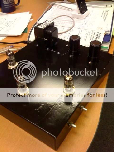
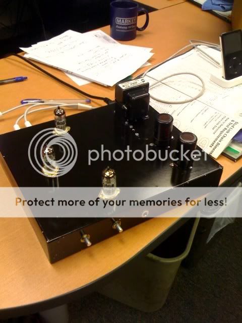
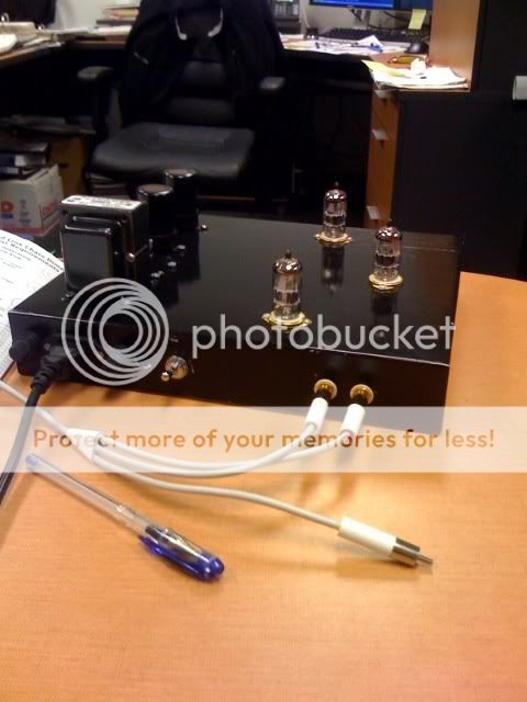
I've just finished the wiring for my 2nd P2P project, the optimized Morgan Jones headphone amplifier with feedback. I've built according to these two schematics:
and the power supply:
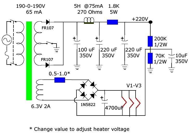
I used a Hammond transformer in my first project (RIAA pre) and was prepared for the B+ and heater voltages to be higher than rated. Sure enough the B+ (unloaded) was ~ 280 VDC and the heater voltage (after rectification) was 9.5 VDC.
The problem I'm encountering now is that I can't seem to adjust the heater voltage down. I've tried increasing the 0.5-1.0 ohm resistor shown in the PS schematic with no effect: 9.5 VDC. I've tried moving the resistor so it's in series after the cap and before the heaters, still 9.5 VDC. I then removed the resistor entirely and am seeing no change: 9.5 - 9.75 VDC across the 4700 microfarad cap.
Obviously there's something I'm missing, but what?
Now most of this measuring was done with no tubes in but I did try with all three in to see if the voltage dropped when the tubes started pulling heater current: the tubes didn't seem to heat and the voltage stayed the same: 9.5 VDC.
Any advice would be much appreciated as this is a long overdue christmas present that is supposed to be delivered tomorrow.
Thanks in advance!
cgrums
I've just finished the wiring for my 2nd P2P project, the optimized Morgan Jones headphone amplifier with feedback. I've built according to these two schematics:
and the power supply:
I used a Hammond transformer in my first project (RIAA pre) and was prepared for the B+ and heater voltages to be higher than rated. Sure enough the B+ (unloaded) was ~ 280 VDC and the heater voltage (after rectification) was 9.5 VDC.
The problem I'm encountering now is that I can't seem to adjust the heater voltage down. I've tried increasing the 0.5-1.0 ohm resistor shown in the PS schematic with no effect: 9.5 VDC. I've tried moving the resistor so it's in series after the cap and before the heaters, still 9.5 VDC. I then removed the resistor entirely and am seeing no change: 9.5 - 9.75 VDC across the 4700 microfarad cap.
Obviously there's something I'm missing, but what?
Now most of this measuring was done with no tubes in but I did try with all three in to see if the voltage dropped when the tubes started pulling heater current: the tubes didn't seem to heat and the voltage stayed the same: 9.5 VDC.
Any advice would be much appreciated as this is a long overdue christmas present that is supposed to be delivered tomorrow.
Thanks in advance!
cgrums
9.5V is an expected "off load" value.Now most of this measuring was done with no tubes in but I did try with all three in to see if the voltage dropped when the tubes started pulling heater current: the tubes didn't seem to heat and the voltage stayed the same: 9.5 VDC.
Clearly the tubes are not properly connected, if the voltage does not come down. Check your wiring.
Heater Volts...
6.3V-AC, will rectify and smooth to 8.9V....
How?
Try this.-- The 6.3V is RMS AC. when you rec and smooth you Times the AC voltage by 1.414 to give the DC voltage. This gives 8.9 odd volts.
In your scheme, why not add the 'dropper' resistor on the DC side, instead of the AC side...?
Using Ohm's law, you can work out the value of resistor to drop the 2.6 odd volts, The Current will be the total drawn by the heaters of all the valves added up......
Adding the resistor on the DC supply to the heaters, will act as a 'surge-limiter' too--All to the good....😀
Alternatively Use a Voltage regulator....🙄
If you use a resistor to drop the heater voltage, split it in half and use one half in series with each feed.
Also, the heaters should be bypassed against common mode noise. A 10nF or so ceramic cap from each heater lead to ground will take care of that, especially if you use some nice inductive resistors for the voltage dropping; they should be placed between the rectifier/filter cap and the heaters/common-mode bypasses.
Also, the heaters should be bypassed against common mode noise. A 10nF or so ceramic cap from each heater lead to ground will take care of that, especially if you use some nice inductive resistors for the voltage dropping; they should be placed between the rectifier/filter cap and the heaters/common-mode bypasses.
Re: Heater Volts...
Depending on the rectification (full- or half-wave) you will lose either 0.8V or 1.6V across the rectifier diodes. So worst case you get 7.3, not counting ripple.... Then, you will only have to lose 1V across that resistor.
Jan Didden
Alastair E said:6.3V-AC, will rectify and smooth to 8.9V....
How?
Try this.-- The 6.3V is RMS AC. when you rec and smooth you Times the AC voltage by 1.414 to give the DC voltage. This gives 8.9 odd volts.
In your scheme, why not add the 'dropper' resistor on the DC side, instead of the AC side...?
Using Ohm's law, you can work out the value of resistor to drop the 2.6 odd volts, The Current will be the total drawn by the heaters of all the valves added up......
Adding the resistor on the DC supply to the heaters, will act as a 'surge-limiter' too--All to the good....😀
Alternatively Use a Voltage regulator....🙄
Depending on the rectification (full- or half-wave) you will lose either 0.8V or 1.6V across the rectifier diodes. So worst case you get 7.3, not counting ripple.... Then, you will only have to lose 1V across that resistor.
Jan Didden
Wow! This forum is fantastic...many thanks to all that have responded.
Right as I left the house this morning I decided to take one more quick look at the wiring....sure enough the tube sockets are wired backwards. I'm going to tackle the rewire as soon as I can escape the office.
Thanks again.
Right as I left the house this morning I decided to take one more quick look at the wiring....sure enough the tube sockets are wired backwards. I'm going to tackle the rewire as soon as I can escape the office.
Thanks again.
After re-wiring the tubes I've been able to adjust the heater voltage down to 6.3V properly.
Now a new problem: upon first firing it up I noticed only 13.0V B+...certainly not the 280+ I was seeing without the tubes present.
I found that the 1.8k 5 watt resistor was dropping ~ 190V and getting extremely hot. All of the preceding voltages in the PS are checking out, why the huge current drawn in that particular resistor? Is this indicative of something downstream?
Thanks in advance.
I suspect the voltage divider to bias the heater is drawing huge current. Check the resistance value, they can be wrong. i.e. lower than what you thought.
Applying Ohms law here indicates that the amp is drawing around 100mA for some reason where it should draw 27mA.
The resistor then has to digest 19W...waay over its rating!
Fred is right, check that voltage divider (and everything else just to be sure).
The resistor then has to digest 19W...waay over its rating!
Fred is right, check that voltage divider (and everything else just to be sure).
Thank you for the suggestions, turns out I had a bypass cap shorted to the chassis. Works blissfully!
Glad that it works now...
I've built the same amp with a different psu a year ago and had my share of little bugs and problems...😉
I've built the same amp with a different psu a year ago and had my share of little bugs and problems...😉
- Status
- Not open for further replies.
- Home
- Amplifiers
- Tubes / Valves
- Need Help Setting Heater Voltage