Hi All. I just bought a wood lathe and want to build a pair of 1Khz Yuichi horns. On the blue print there is a center line that is ticed off at some increment but I can't figure out what the increment means.
See the pic below. The increment starts at 4 and ends at 16. I've been reading blue prints for years and have never seen where a segment is not marked for length.
See the pic below. The increment starts at 4 and ends at 16. I've been reading blue prints for years and have never seen where a segment is not marked for length.
Attachments
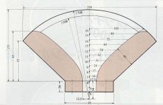
The Tic marks are the width of the horn from the center in MM.
Note the 6 mm from the throat is 12.5 mm (total 1 inch diameter)
At to 10 mm from the throat, the radius is 31mm
At 14 mm from the throat, its 75 mm radius ( about 6 inches diameter)
Note the 6 mm from the throat is 12.5 mm (total 1 inch diameter)
At to 10 mm from the throat, the radius is 31mm
At 14 mm from the throat, its 75 mm radius ( about 6 inches diameter)
I see what you mean. Could they be Centimeters?
Clearly the 4 to 6 in the throat is labeled "20" on the outside of the horn.
So the throat depth is 20 mm, the center-line starts at 0, which is the zero point for the 170 mm radius.
Clearly the 4 to 6 in the throat is labeled "20" on the outside of the horn.
So the throat depth is 20 mm, the center-line starts at 0, which is the zero point for the 170 mm radius.
I thought I'd have a go at doing this drawing to scale, and it doesn't seem to work out at all? The 104mm line doesn't reach the outer radius if those are supposed to be cm up the middle. (edit: whoops, made a mistake, fixed, but same problem still)
Attachments
Last edited:
Your drawing sure does help DT. I think the numbers are markers not measures. So if I start at the crosshairs and count my 10cm for each station marker, it seems to get close to working out. I agree though, that the drawing is not right.
I can whip one up out of plywood and measure it.....sound wise.
I can whip one up out of plywood and measure it.....sound wise.
Yep, I get that Doug, but I don't think that the station marks on the CL is mm.
Hmm, the distance from the focal point to the beginning of the flare is 34 mm and is [3] segments long, so seems it's 34/3 = 11.3333 mm between segments, but in the metric world this begs the question: 'why'?
GM
Heh, well, I've still got this drawing open and that's easy to do... It doesn't seem to work out any less odd. I'm not sure where you're getting 3 segments for that, though, as no '0' mark is definite. Meanwhile, the 20mm deep section is clearly two segments, bringing it back to 1cm per segment.Hmm, the distance from the focal point to the beginning of the flare is 34 mm and is [3] segments long, so seems it's 34/3 = 11.3333 mm between segments, but in the metric world this begs the question: 'why'?
Attachments
Last edited:
Hmm, the distance from the focal point to the beginning of the flare is 34 mm and is [3] segments long, so seems it's 34/3 = 11.3333 mm between segments, but in the metric world this begs the question: 'why'?
GM
But then look at the segment between 4 and 6. Off to the left it indicates it is 20mm. So the segment between the crosshairs and 4 must be 14mm.
I just added to the CL with section 17, 18, and 19. Making the assumption that the section between the crosshairs and 4 is 14mm, and the sections are 10mm each, the total is 170mm just like the radius.
I'm trying to read it (in my metric universe) and doesn't show the starting point for segment #4. It should be/read 40 (something) if 1x segment = 10 (mm or something). (10 mm = 1 cm)Hmm, the distance from the focal point to the beginning of the flare is 34 mm and is [3] segments long, so seems it's 34/3 = 11.3333 mm between segments, but in the metric world this begs the question: 'why'?
GM
It shows only starting/ending point for measurement 34 (mm).
This for some reason shows that the source/starting point for segments #1, #2, #3, #4... it's not the same as the measurement (or segment) of 34 mm. In my logic world 1x segment #4 = 40 mm, away from "segment 34". Don't ask me why... 🙁
I must admit that, if that's the beginning of measurement of segments, it's very logic. I just taught #4 was preceded by number 3, 2 and 1. Where are they?!But then look at the segment between 4 and 6. Off to the left it indicates it is 20mm. So the segment between the crosshairs and 4 must be 14mm.
The image attached in post #1 is not quite to scale. Except for one of the radial dimensions of the horn curve, the numbers seem consistant (the red segment shows where the curve is concave).
Dimensions are in mm except for the axis which is in cm. the centre of the arcs is at 2.6 cm
dave
Dimensions are in mm except for the axis which is in cm. the centre of the arcs is at 2.6 cm
dave
Attachments
Heh, well, I've still got this drawing open and that's easy to do... It doesn't seem to work out any less odd. I'm not sure where you're getting 3 segments for that, though, as no '0' mark is definite. Meanwhile, the 20mm deep section is clearly two segments, bringing it back to 1cm per segment.
Oh well........ From the drawing. I did say from the focal point, i.e. the radius arc and there's only one...... Yes, I noticed the discrepancy, but didn't know if the drawing was to scale, but figured you'd try it on your drawing, so nothing ventured, nothing gained. 😉 Anyway, it wouldn't be the first drawing ever done in multiple scales for tooling purposes or drawn over a scaled grid that I'm not familiar with.
GM
Unfortunately, this is all they have for measurements. But here is the full print.
Why not just print out these plans full scale so that throat measures 25.5mm on the physical print. Then use a pair of calipers to carefully measure what the actual dimensions are every 1cm out. Seems like the best way to eliminate guess work, assuming the drawings are accurate of course.
Dimensions are in mm except for the axis which is in cm. the centre of the arcs is at 2.6 cm
OK, so the segments begin 3 cm behind the focal point, but what arcs are at 2.6 cm, the ones at the mouth corners?
GM
OK, so the segments begin 3 cm behind the focal point, but what arcs are at 2.6 cm, the ones at the mouth corners?
The centre/origin of the arcs are at 2.6 cm on the vertical axis, 14mm below the opening.
dave
- Status
- Not open for further replies.
- Home
- Loudspeakers
- Multi-Way
- Need help reading blue prints for wood horns.