Problem : wich of the following part is the good one in datasheet?I`ve found 2 . I believe the second part found after the search on datasheet is the good one.No?Post the DC voltage on all of the pins of the one with 7.65v on the output.
IC#
Pin 1: 14.75 - 8.85
Pin 2: 0.04 - 8.04
Pin 3: 0.0 - 8.95
Pin 4: 0.01 - 8.60
Pin 5: 14.71 - 8.75
Pin 6: 0.01 - 8.65
Pin 7: 0.01 - 8.90
Pin 8: 0.04 - 7.88
Pin 9: 14.62 - 8.90
these are the values given up on the multimeter.Set to 20V DC.The values shown are on both op-amps.the one with 7.65 is the second column.
Now the values shown are with signal input given to the amp and they are approximate.
Last edited:
Don't use a hyphen as a separator. It can be taken as a negative sign.
Some of the pins should have been negative voltage (unless all of the second column is negative).
Copy and past the list I provided for each op-amp and re-list the values including a negative sign (hyphen) for the ones with negative voltage. Include the IC number. There are 3 op-amps (IC851, IC451, IC551). Do not drive an audio signal into the amp for these tests.
I`ve found only 3 such op-amps.
1-st IC452 - just after the rca inputs
1)14.83
2) 0.00
3)-0.00
4)0.00
5)-14.85
6)0.00
7)0.01
8)0.01
9)14.83
2-nd IC551
1) 14.85
2)-0.05
3)0.00
4)0.00
5)-14.82
6)0.00
7)0.00
8)0.03
9)14.73
3-rd
1)8.90
2)8.45
3)8.90
4)8.47
5)8.92
6)8.43
7)8.90
8)8.20
9)8.90
On the 3-rd one I did not get any negative voltage .
p.s.
the values 0.00 that are negative (- 0.00 and only these ones i`m refering to ).....i don`t know what to say about the - sign .because it kept flashing...it appeared it disappeared, and not in the kind of way that it did on the -14.85 V.I mean it disapeared for lets say 3-4-5 seconds to 10-15 if I counted and it appeared for less then 1 second when it did appeared.So i`m not sure what to say about it.could be an eror or my hand moving...tremurs.
Last edited:
If it's still in the vehicle, plug in the RCAs and see if the voltage changes significantly on IC851. If it does, post the new voltages.
If it's still in the vehicle, plug in the RCAs and see if the voltage changes significantly on IC851. If it does, post the new voltages.
i don`t have a IC851 as presentet in the schematic.
only IC i got that are op-amp are the 3 i have just posted.
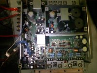
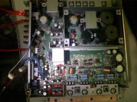
there are 2 on the main-board with the output transistors (their the long dark pieces in line with the output transistors and the one above), and only 1 IC (IC452) on the inputs, seen in the last picture attached. I cannot find anyother.If they are of diffrent form please let me know.
as I can only guess, the differente between the schematic and what is acctualy on the mainboard is due to the fact that I guess the schematic is for GM-1200, and not Gm-2200.Therfore there are a little bit of differences.
But on the input "line" there is only one IC.
As I can tell ti`ll now.
Attachments
![P04-11-11_23.55[01].jpg](/community/data/attachments/236/236319-551fda268d6181c8e51d8c8688f1cd82.jpg?hash=VR_aJo1hgc)
![P04-11-11_23.56[04].jpg](/community/data/attachments/236/236345-ba4f5e4512824d1a6b0f64b98de22f71.jpg?hash=uk9eRRKCTR)
Last edited:
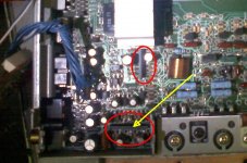
the op=amp indicated with the arrow , its use is in the left channel.
and this is the one with no negative voltage reading.
and this is the one with no negative voltage reading.
Does the voltage on it change when you plug the RCAs in?
ok.connected rca
1-st case, with rca pluged in an no input, (I got the same values with no rca pluged in as well)
8.60
7.80
8.50
8.07
8.50
8.07
8.55
7.80
8.60
2-nd case with rca connected and signal input from 1.5 v source.
8.75
7.55
8.75
8.67
8.30
8.45
8.75
7.35
8.75
these are the values.
Last edited:
Disconnect the RCAs and measure the resistance from the RCA shield on the amp to pin 5 of the op-amp in the previous post (#69).
Disconnect the RCAs and measure the resistance from the RCA shield on the amp to pin 5 of the op-amp in the previous post (#69).
ok.got a 0.08 ohm reading.
i`ve tested the other op-amp as well.there I didn`t get any readying on the same test.
I get a reading of 0.8 ohms on both rca shields.I think that is ok no?I don`t need to make that connection with the HU chasis correct?
I read on your page ...I think step 4 ( Amp in Protection - Troubleshooting )
And It says "You need to power up the amplifier and measure the voltage on the shields (shiny outer metal ring) of the RCA jacks. Touch the black meter probe to the ground terminal of the amp and the red meter probe to each of the RCA shields. If you read 10v or more, the amplifier may have a shorted transformer. If you read something less than 1v, the transformer is likely OK."
I`ve done this and I get a reading of 8.40 V on both RCA input plugins of the amp. (no rca cable connected, just tested on the rca shields of the amp )
Could It be posible to have a bad transformer?How can I check this in depth?
Is the head unit grounded to the same ground as the amplifier?
If not, connect the two grounds.
The amp ground is the ground terminal.wich connects with the - of the battery.
The HU ground is the screw on the chasi.
How do I connect the amp to the same ground with the HU ??
Do I need to make the connection (is this the connection you are suggesting?):
cables "glued" to the RCA shiled - ground screw on the HU chasi
cables "glued" to the RCA shiled of the amp - ground screw on the HU chasi
If I am not understading please explain to me as to a complet ....n00b. I wi`ll not find it offensive.
nope.for the moment its not in the car. Beacuse of the testing it is more easy to not be conected in the car.
i`m testing it on a car battery I have it in the house.
i`m testing it on a car battery I have it in the house.
nope.
I read there that its best to keep them power off.And not on.I just pooped it out and checked them as indicated.
I got 0.8 ohm as related.
The testing was with no power .
I read there that its best to keep them power off.And not on.I just pooped it out and checked them as indicated.
I got 0.8 ohm as related.
The testing was with no power .
The head unit needs to be powered from the same power supply/battery as the amp. If they're on separate supplies, the grounds need to be tied together.
- Status
- Not open for further replies.
- Home
- General Interest
- Car Audio
- Need help ! Pioneer GM-2200