I have a Threshold M7 power supply that is not working. I have tracked to problem down (I think) to a few transistors, one which I can't seem to find an equivalent for. The marking are:
NS
310-2
7402
Anyone know of a replacement?
Thanks for any help.
NS
310-2
7402
Anyone know of a replacement?
Thanks for any help.
Attachments
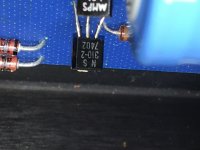
NS = NatSemi, 7402 = 2nd week 1974. Have found a few references to NS3101, nothing with type or data. Lost to the sands of time? Reverse engineer the circuit or stick in some modern regulator chip(s)?
Would that leave 310-2 as the part #?
Thanks
** Checked. Can't find any info. on a transistor with that model #.
Thanks
** Checked. Can't find any info. on a transistor with that model #.
Last edited:
310-2 is probably an abridged house-number for Threshold, like the ones used by HP, Tek, Philips, etc.
For example 151-something is normally a transistor in the traditional Tek numbering.
It is sometimes possible to find translation tables, unless the device was really intended for that specific manufacturer and has no equivalent
For example 151-something is normally a transistor in the traditional Tek numbering.
It is sometimes possible to find translation tables, unless the device was really intended for that specific manufacturer and has no equivalent
1) why do you think the problem is that transistor?
You must troubleshoot the circuits (i.e. functionally test it, measure voltges, etyc.).not replace parts at random.
2) that is probably a garden variety general purpose small signal transistor, just check whether its NPN or PNP.
Check voltage on its pins.
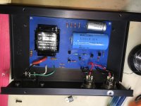
3) if anything I would worry much more about a 1974 vintage electrolytic, such as the 1100uFx50V seen there.
And the 100x50 besides it.
Again, first troubleshoot, then replace as needed.
You must troubleshoot the circuits (i.e. functionally test it, measure voltges, etyc.).not replace parts at random.
2) that is probably a garden variety general purpose small signal transistor, just check whether its NPN or PNP.
Check voltage on its pins.
3) if anything I would worry much more about a 1974 vintage electrolytic, such as the 1100uFx50V seen there.
And the 100x50 besides it.
Again, first troubleshoot, then replace as needed.
It is sometimes possible to find translation tables
I ran into the same issue with "House Number" while working on the Threshold 4000. Fortunately, those numbers seem to have been researched by many and are readily available online.
Anyone have any reference info from Threshold for this part # from Threshold?
JMFahey, I did go through and test parts. I have a working M7 I was using for comparison which helped. Unfortunately, I didn't find a single part that could explain the issue. So, since it's a regulated power supply, I followed the path. The issue is no output. I found that the output dropped to a few mV instead of the regulated 18 Vdc past the IC regulator. There are also 2 transistors in the path that may have contributed to the failure of the IC reg. or may have failed due to the IC reg. failing. Since the cost of transistors is usually a fraction of the shipping cost, I thought I'd get all 3 parts at once, just in case. I'd hate to miss a part and have to pay shipping for such an inexpensive part or worse yet, blow my new part due to an issue with another bad part I didn't swap out.
This is all hobby for me, I'm not an expert. Any advice would be appreciated.
Caps are getting replaced. But, right now they test OK (except for the small Tantalum cap, but it isn't anywhere in the circuit where it would cause no output ... I think!)
Thanks
** Just noticed, in the full picture above, I had already removed the IC regulator. See the 3 empty holes.
Caps are getting replaced. But, right now they test OK (except for the small Tantalum cap, but it isn't anywhere in the circuit where it would cause no output ... I think!)
.
Tants can go short circuit.
Tants can go short circuit.
This one is actually reading about 20 uF while rated at 4.7.
This one is actually reading about 20 uF while rated at 4.7.
Not necessarily a good thing, I'd replace it.
Not necessarily a good thing, I'd replace it.
Oh yes, it's getting replaced with the other 2 caps. Just hoping to find out what the heck that last transistor is so I can order all together.
As I look at the specs of, what I thought was an, IC regulator, I'm noticing they call it a transistor. Maybe I'm just mixing names. It's position in the circuit implies it regulates.
what I thought was an, IC regulator, I'm noticing they call it a transistor.
Maybe I'm just mixing names. It's position in the circuit implies it regulates.
Can you reverse engineer the schematic?
A transistor can regulate voltage, with supporting components.
Last edited:
Agree.
That power supply looks quite simple.
Yes, it's not necessary to identify the unknown parts, just number the pins.
Some holes are unpopulated, and there may be jumpers etc. underneath.
Last edited:
Can you reverse engineer the schematic?
A transistor can regulate voltage, with supporting components.
That's what I was thinking. I'm not good enough at this to reverse engineer it. I could probably draw up a schematic of it. (Not a bad idea, there may be others out there looking for an M7 schematic, it might be nice to get one out there).
There are 2 jumpers under the board.
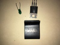
The unpopulated holes are where I removed one transistor and the tantalum cap.
The tansistor is: 7832TO / FT317
I was going to replace with: MJE15030G
I'll post a picture below.
Thanks for the help, I appreciate it. Would anyone be able to tell anything from a schematic? 25 components and 2 jumpers, I think I might be able to handle that.
Attachments
Would anyone be able to tell anything from a schematic?
Yes, definitely. Just number the pins of each part, whether or not the part number is known.
Also the polarity of capacitors and diodes. Don't replace any parts yet, the semis may not be
what you think they are.
Last edited:
I got some more info. from a Threshold Pro I met a while back. I ended up replacing:
the 7832TO / FT317 with a MJE15030G
the AAMPS LO1 with a 2N5550
the NS 310-2 7402 with a J310
and all the caps
I got an output voltage of 21.5 vdc.
My other M7 (working / original) has an output of 19.5 vdc.
Thinking I missed something, I pulled all the resistors, diodes and 3 remaining transistors from the board and tested. They all were fine.
I then swapped the 3 new transistors from the repaired unit into the original / working unit. I also replace the 3 caps in that unit as well.
Voltage didn't change much:
Repaired unit 21.47 vdc
Working / original unit 19.6 vdc
That's about a 10% difference in a regulated power supply. Seems high. Is anyone familiar with these PS, is that acceptable for use with the Threshold M1? (what this was basically designed for).
Or, should I keep searching for an issue.
Thanks
- Home
- Amplifiers
- Power Supplies
- Need HELP identifying a transisitor