Hi,
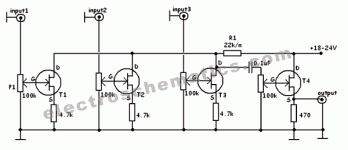
I’m quite new on analogue electronics. I found this schematic for a audio line mixer, but I can’t understand something... maybe someone could help me:
1) Why audio signal pass on drain level on t1-t2-t3 but on source level on t4?
2) Why is not present another capacitor to filter dc - ac on output line after t4?
3) why r1 is after t4 and the resistor on the source of t4 has a different value respect the other resistors?
Thank you for your help... I’m try to learning but eletroninc is not so easy...

Attachments
Its a bit of a strange circuit, however,
Lets start with T4. This is a 'source follower' which is a bit like an emitter follower. It is used as a buffer with voltage gain of a little less than '1'. It enables low impedance loads to be driven.
There should be a cap after T4 (well, spotted 🙂)
Lets take a look at just one of the other stages, T1, T2 or T3. All three are the same. These are configured as amplifying stages and based on a 'common source' configuration.
AMP I.10 – The Common Source Amplifier
R1 is common to all the three input stages in this design (how well that works as a mixer I wouldn't like to say...) and these stages also invert the signal by 180 degrees.
So the 'mixed' signal voltage appears on R1 and is then fed to the buffer stage.
I've never looked at that site so can't really comment. There is probably a mix of good, bad and indifferent designs on there.
https://www.electroschematics.com/3-channel-audio-mixer/
Same website, much more conventional circuit, easy to build. You could simplify it even more.
This assumes you have basic op amp skills.
Same website, much more conventional circuit, easy to build. You could simplify it even more.
This assumes you have basic op amp skills.
I was going to tell him to use the 5532, if he gets that far.
That circuit is just an example of a more conventional circuit. I'm just trying to show what a simple, conventional layout looks like.
I personally don't think an op amp based 3 channel mixer is a good circuit for a beginner. You need to start with a much simpler circuit.
That circuit is just an example of a more conventional circuit. I'm just trying to show what a simple, conventional layout looks like.
I personally don't think an op amp based 3 channel mixer is a good circuit for a beginner. You need to start with a much simpler circuit.
indeed an interesting schematic.basically it consists of voltage to current converters using a simple fet. rodec once had a dj mixer based on that principle. the advantage over pure resistive mixing and opamp based mixing is that there is a much lower noise contribution of the summing stage, as the summing stage noise is amplified by the number of channels connected, in opamp summers. indeed a simple and clever circuit.
as the fet V->I stage has a high output impedance, the noise contribution is just the sum of the noise of the V/I stages. not bad.
as the fet V->I stage has a high output impedance, the noise contribution is just the sum of the noise of the V/I stages. not bad.
Last edited:
- Home
- Source & Line
- Analog Line Level
- Need help for understand mix schematic
