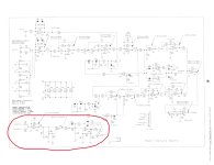
See the attached circuit circled in red. The circuit senses a signal and provides -12V for on and +12V for off, just the opposite of ICEPower modules. I am wanting to have the circuit provide +12V for on and 0V for off. A little more complicated than a simple flip flop. Any ideas? I can build a simple circuit on a breadboard and piggyback off the +-15V to power it.


Thank you so much. I hadn't thought about just using a transistor, that makes sense. I was locked into a simple opamp. Pretty sure the load is insignificant. Class D amp I'm wanting to use shows a 47k resistor in series with the internal circuitry.
Not working with the 2N5551. Switches between 9V and 10V. I'll get some 2N2222A in my next Mouser order.
Rayma's solution should work with any transistor. Are you sure the transistor is connected correctly?
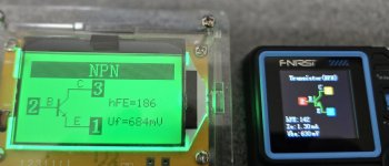
Yeah, test the transistor with your DVM diode function before installing it.
Double check the lead pinout, E - B - C (left to right).
Double check the lead pinout, E - B - C (left to right).
Wish I could, but the opamps are quads.Flip D111 and swap +/-15 for on/auto.
Don't touch the op-amps. Just the diode and the switch wiring.Wish I could, but the opamps are quads.
- Home
- Design & Build
- Electronic Design
- Need help designing a simple flip flop for 12V trigger

