I bought some of the Tangentsoft ps to power my DAC. Problem is in their kit form the lowest output is 12VDC. I need 9VDC for my dac. (+/-/+)
I can't seem to figure out the R2 resistor I would need plus the proper VSET. I'm thinking R2 would be ~750R but maybe R1 should change as well. I'm not good at all the math. Building it I'm fine.
http://tangentsoft.net/elec/tread/misc/sch-v1.1.pdf
I can't seem to figure out the R2 resistor I would need plus the proper VSET. I'm thinking R2 would be ~750R but maybe R1 should change as well. I'm not good at all the math. Building it I'm fine.
http://tangentsoft.net/elec/tread/misc/sch-v1.1.pdf
Leave R1 at 120R, make R2=500R and keep the VSET=500R.
The you can adjust between app. 6 to 12V out.
The you can adjust between app. 6 to 12V out.
Thanks Jan!
Any chance you're good at calculating proper transformer specs?
I would run one pair with one transformer for bipolar operation to feed the analog +/- of the dac board and one supply with its own trans for the digital +
One transformer must have dual secondaries for the analog section, and one feeding the digital side can be a simpler type. I been flailing at numbers at the moment.
I'm not quite sure what you're asking for, however your analog transformer should give 2x12 to 15VAC out in order to achieve full 6-12VDC regulation. I don't know the Current comsumption of your DAC, however even a trafo of a few watts should be enought.
Please correct me anyone, if you know this DAC.
Please correct me anyone, if you know this DAC.
I guess my first reply didn't take. If it does in a while sorry in advance for the double post.
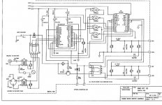
The Dac board is an Audio Note and I'm uploading the schematic. I calculated the current draw by taking the input voltage 9VDC/output resistor (330R) and got 27mA.
Here's a schematic of how I want to run two of the boards in bi-polar for the digital board Analog +9/-9 and the illustrating the type of transformer I need http://tangentsoft.net/elec/tread/pguide.html#dual
Also need one to run one board that will feed the digital +9VDC and ground
Attachments
My guess is that you will never achieve 9V on the output (maybe more like 4V max).....
Perhaps someone knows this DAC ?
Perhaps someone knows this DAC ?
A friend said I could measure by putting DMM leads in series from input to output.
I put one end on the input and the other on the output and I got 12VDC! Huh?
I put one end on the input and the other on the output and I got 12VDC! Huh?
You must have misunderstood something, because that measurement tells you nothing.......
The interesting Voltage measurement here is, what you can measure accross the 330R in the output at full ourput.
Sadly the schem you have attached is to blury to see all details in the circuit when enlarged.
The interesting Voltage measurement here is, what you can measure accross the 330R in the output at full ourput.
Sadly the schem you have attached is to blury to see all details in the circuit when enlarged.
I did misunderstand. I can take that measurement if you like. Also I will upload the larger size as I had to reduce it for this board.
I just uploaded it here http://hipnoticinc.com/dac_dig.jpg
I just uploaded it here http://hipnoticinc.com/dac_dig.jpg
Now I'm confused 😕
The supply shown in your scheme is +/-5V analog, and 5V digital (which also is the max. supply Voltage stated in the Analog Devices datasheet for the AD1855) ?
The supply shown in your scheme is +/-5V analog, and 5V digital (which also is the max. supply Voltage stated in the Analog Devices datasheet for the AD1855) ?
Ok... Not shown in the schem....
The datasheet for the AN1855 states max. 35mA consumption for analog and 24mA for the digital.
The datasheet for the AN1855 states max. 35mA consumption for analog and 24mA for the digital.
The scan is hard to read the chip. Its a 1865 Chip. Also I just measured and that's about what I got.
- Status
- Not open for further replies.
- Home
- Design & Build
- Parts
- Need help calculating parts for Tangentsoft PS