Hi,
I bought a Philips console a while ago with the intent of making a stand-alone power amplifier with the insides. It's a little 2-channel, SE, 6GW8 outputs with a single 12AX7 driver, EZ81-rectified. OPT's are small-ish, but that's OK as it might end-up driving Minimus 7's or even super-tweeters.
Being stuck on the same chassis as the tuner, I decided to rebuild the whole amp in a cast aluminium Hammond enclosure. All resistors and capacitors are new, tube sockets are new. I only kept transformers, power and OPT, and tubes, since the console worked. I eliminated the volume control/loudness, tone controls and balance control.
I got done with the wiring and building a few days ago, but have since been working on finding the cause of it's problem. What happens sonically is that sound will play by small bursts, every 3-4 seconds or so. What happens electically seems that the output tubes, 6GW8 are conducting ON and OFF, switching every 3-4 seconds, affecting B++++. More specifically, it seems to be the pentode section only that does that.
If I remove BOTH 6GW8 from their sockets, B++++ is now stable, at a high value of ~340VDC. Removing a single 6GW8 does not stop this problem, nor does removing the 12AX7.
My voltages seem to be higher than what is spec'ed on the schematic, perhaps due to lighter loads, with tuner/TT removed, and modern mains voltages. The secondary of the power transformer supplies 2x 250VAC instead of 2x 225VAC, leading to the higher DC supply voltages as well.
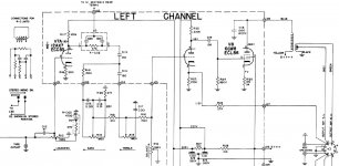
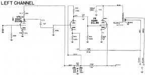
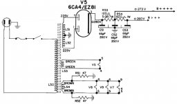
I attached the original schematic for one channel, as well as the revised power supply and power amplifier section schematics as I assembled them, with the new values of components. The voltages reading on there are the original values and not the ones I am getting.
One thing that I know is wrong at the moment and that I will fix, is the first capacitor in the supply filter, 68µF. It should not be over 50µf for the EZ81 rectifier, but that is not the cause of my problem, at least not that alone.
I am quite new to tubes, having done one succesful console amp conversion so far, this is my second. I appreciate any help analyzing my schematic, as I may have gotten something wrong without realizing it.
Also, my lead dress/assembly under the chassis is a bit of a mess, I could expect some hum or something I guess, but doubt it could be cause for what I'm getting.
That's pretty much all the info I can give at the moment, at the top of my head, if you need to know something, don't hesistate to ask; I'm starting to run out of ideas of what to check for.
Thanks in advance!
IG
I bought a Philips console a while ago with the intent of making a stand-alone power amplifier with the insides. It's a little 2-channel, SE, 6GW8 outputs with a single 12AX7 driver, EZ81-rectified. OPT's are small-ish, but that's OK as it might end-up driving Minimus 7's or even super-tweeters.
Being stuck on the same chassis as the tuner, I decided to rebuild the whole amp in a cast aluminium Hammond enclosure. All resistors and capacitors are new, tube sockets are new. I only kept transformers, power and OPT, and tubes, since the console worked. I eliminated the volume control/loudness, tone controls and balance control.
I got done with the wiring and building a few days ago, but have since been working on finding the cause of it's problem. What happens sonically is that sound will play by small bursts, every 3-4 seconds or so. What happens electically seems that the output tubes, 6GW8 are conducting ON and OFF, switching every 3-4 seconds, affecting B++++. More specifically, it seems to be the pentode section only that does that.
If I remove BOTH 6GW8 from their sockets, B++++ is now stable, at a high value of ~340VDC. Removing a single 6GW8 does not stop this problem, nor does removing the 12AX7.
My voltages seem to be higher than what is spec'ed on the schematic, perhaps due to lighter loads, with tuner/TT removed, and modern mains voltages. The secondary of the power transformer supplies 2x 250VAC instead of 2x 225VAC, leading to the higher DC supply voltages as well.
I attached the original schematic for one channel, as well as the revised power supply and power amplifier section schematics as I assembled them, with the new values of components. The voltages reading on there are the original values and not the ones I am getting.
One thing that I know is wrong at the moment and that I will fix, is the first capacitor in the supply filter, 68µF. It should not be over 50µf for the EZ81 rectifier, but that is not the cause of my problem, at least not that alone.
I am quite new to tubes, having done one succesful console amp conversion so far, this is my second. I appreciate any help analyzing my schematic, as I may have gotten something wrong without realizing it.
Also, my lead dress/assembly under the chassis is a bit of a mess, I could expect some hum or something I guess, but doubt it could be cause for what I'm getting.
That's pretty much all the info I can give at the moment, at the top of my head, if you need to know something, don't hesistate to ask; I'm starting to run out of ideas of what to check for.
Thanks in advance!
IG
Attachments
First thing I'd do is break the feedback loop, then take voltage measurements with no input signal (Input disconnected,not turned off).
Look at the B+ voltage to see how much it varies.
Do any of the grid voltages seem to be switching with no input?
Leaky C119 could cause problems.
What is C118? Ceramic disk?
What are you driving it with? You are DC coupled on the input. Could your source be biasing the first triode (V7A)?
Look at the B+ voltage to see how much it varies.
Do any of the grid voltages seem to be switching with no input?
Leaky C119 could cause problems.
What is C118? Ceramic disk?
What are you driving it with? You are DC coupled on the input. Could your source be biasing the first triode (V7A)?
C119 should be 0.01uF (10nF) according to the original schematic, this alone could account for the instability issue depending on how badly behaved the OPTs are at very low frequencies. (Lots of phase shift I'd suspect)
Other possibilities include inadvertently swapping either the primary or secondary connections on your OPTs.
Also some pictures of your chassis and layout would be helpful to determine whether or not you have made obvious mistakes in layout and construction approach.
You don't need that first 12AX7A at all now that you have removed all of the losses resulting from the tone controls, and if you retain it gain will be ridiculously it high. In addition that 1uF coupling capacitor is far too large - it should be no large than 0.1uF. The amp on its own has more than 20dB of gain - quite sufficient for any use to which you would put it, and probably excessive in its own right. (Add attenuation in front if that is the case, do NOT change the feedback resistor value.)
Last edited:
Wow, good advice guys! Things I sort of know, but did not consider. 😱
kevinkr:
By using bigger coupling capacitors I was hoping to achieve better LF characteristics, but did not think about the fact that they might serve the purpose of limiting bad behavior of the OPT, which probably are limited in that department to start with, so I will try restoring to new 10nF units.
About OPT connections, or any other connection for that matter: they are correct. I went over them I don't remember how many times! 🙂
About the amp's gain: it is really high indeed. During the short bursts of music that make it to the speakers, it is quite loud considering the -40dB VC setting on my CDP's variable output.
TheGimp:
About the input DC coupling: my other tube amp is the same and never suffered problems with this factor, but it's worth checking, as it's simple enough to try. I'll also check my source's output for any DC component.
C118 is Polypropylene. Coupling caps are Polyester.
I'll try the test you suggested.
Thanks!
IG
Hi,
My voltages seem to be higher than what is spec'ed on the schematic, perhaps due to lighter loads, with tuner/TT removed, and modern mains voltages. The secondary of the power transformer supplies 2x 250VAC instead of 2x 225VAC, leading to the higher DC supply voltages as well.
IG
You are correct here in your analysis. You may add a 100 ohm (give or take) 5 watt resistor between the rectifier and the first cap to drop the voltage to spec and you can add a 47uf cap before that resistor too for some additional filtering.
Or you can check the data sheet to see if the power tubes can live with the higher voltages. If so, you can increase resistance in the subsequent dropping resistors to bring your twin triodes down to spec. Either approach is just fine. Just remember to rebias the power tubes for the higher voltage.
I'm a big fan of console pulls. They are a great way to experiment and build experience without significant investment. Stay safe.
I'd prefer leaving B++++ as close to 273VDC as I can, as I won't need more power with this amp and also these 6GW8 are quite expensive! I want to go easy on them!
I might do as you suggested and add an input smoothing cap of 47µF and pad the voltage down with resistance before the current filtering stages.
Yes, console pulls rock! I love my 6BQ5 PP from an RCA/Victor I did last winter. This is my second project as mentioned before. I can buy the consoles for 20-30$ and buy parts for anything from 10$ to 100$ and have a nice stand-alone tube amp.
Thanks for the advice!
az
Hehe, I calculated a bit and realised the sheer folly of putting 1µF coupling capacitors, as 10nF is already much more than enough for the job, considering the small size of the OPT's!
Live and learn! 😀
IG
Live and learn! 😀
IG
Given that you are not runing into grid current (class 2), coupling cap sizing is related to the capacitance of the driven tube (minor effect), and the grid resistor value (biggest factor). The larger the grid resistor, the smaller the coupling cap can be for the same lower frequency -3dB point.
You have a fairly large grid resistor (825K) so the cap can be relativly small.
with 10nF and 825K, 1/( 2 pi R C) puts it at 19.29Hz
I got a console to salvage because I was curious about how good (or bad) they actually sounded compared to what I remember from my youth. Unfortunatly the Webcor I got has a bad output transformer on one channel so I'll be replacing them with EDCOR XP10-8-8K transformers. At $17.22 each they actually have a better frequency response and efficency than the original tranformers did.
Aside from the risk of having bad parts from wear and tear, the other risk I've found with console systems is that a good many of them were 16 Ohm output. They can drive 8 ohm speakers but you get more distortion and lower power out.
Last edited:
Given that you are not runing into grid current (class 2), coupling cap sizing is related to the capacitance of the driven tube (minor effect), and the grid resistor value (biggest factor). The larger the grid resistor, the smaller the coupling cap can be for the same lower frequency -3dB point.
You have a fairly large grid resistor (825K) so the cap can be relativly small.
with 10nF and 825K, 1/( 2 pi R C) puts it at 19.29Hz
Yeah, exactly the number I got. 0.1929Hz for my current 1µF cap. Kinda ridiculously overkill. The OPT probably won't even come near being efficient at even 20Hz.
Given that what I get is some kind of super low frequency, ~3-4Hz, oscillation, that could well be where my problem (and mistake 🙂) lies.
IG
Last edited:
I got a console to salvage because I was curious about how good (or bad) they actually sounded compared to what I remember from my youth.
Me too. I picked up an old GE console at a yard sale this spring. I plugged it in and tested it, and peeked through the backing board to see the tubes all glowing. When I got it home I discovered the amplifier section was solid state and the tube section was the tuner/preamp. So all I really ended up with was a small power transformer and a handful of well-used tubes. Next time, more due diligence; things are not always what they seem. 🙄
..Todd
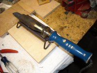
If you are going to work on old consoles, you might want to look for one of these at yard sales.
This one is 300W, and probably bigger than needed. 200W would be fine even for big guitar chassis.
As cool as that big ol' iron looks, what would be a console-specific use for such high power?
BTW, I did not have time to implement any of the previously mentioned solutions to my problem last night, hope I got time tonight and during weekend.
IG
A lot of these old systems used the chassis as ground for the system. I prefer to not connect components to the chassis as it can create hum issues.
Removing grounds to the chassis that are soldered in place so one can create a Star ground system or ground bus.
De-Capping / Re-Capping chassis mounted caps that are soldered in place. Re-Capping is better done with clamp in caps if possible but some times the multisection cap selection is better with twist lock tab caps.
I've got a 100/140W Weller solder gun, but it just does not have the heat capacity to do the job. The tips don't have enough thermal mass to heat the sheet metal chassis effectivly.
Good luck on the oscillation problem. It does indeed sound like a feedback oscillation through the B+ filter caps.
This article on Pete's web site has some discussion about it, eight article from the bottom "Amplifier Response Stability & All That" By John Moyle:
Vintage data
Second half of the article, page 39 under "PHASE CHANGES" is the discussion about low frequency oscillations.
A lot of these old systems used the chassis as ground for the system. I prefer to not connect components to the chassis as it can create hum issues.
Removing grounds to the chassis that are soldered in place so one can create a Star ground system or ground bus.
De-Capping / Re-Capping chassis mounted caps that are soldered in place. Re-Capping is better done with clamp in caps if possible but some times the multisection cap selection is better with twist lock tab caps.
I've got a 100/140W Weller solder gun, but it just does not have the heat capacity to do the job. The tips don't have enough thermal mass to heat the sheet metal chassis effectivly.
Good luck on the oscillation problem. It does indeed sound like a feedback oscillation through the B+ filter caps.
This article on Pete's web site has some discussion about it, eight article from the bottom "Amplifier Response Stability & All That" By John Moyle:
Vintage data
Second half of the article, page 39 under "PHASE CHANGES" is the discussion about low frequency oscillations.
Makes sense. The first amp I did had one or two soldered chassis grounds IIRC, that I either left as is or desoldered with my ~1/8 tip Hakko 936. Probably I had to let it stand there for a while before anything melted. 🙂
Yeah, I think the way-oversized coupling caps may be letting some initial B++++ oscillations in the circuit and amplifying them. I'll go buy some 10nF caps during lunch.
IG
As mentionned before, the amps does have way too much gain. I could certainly attenuate the signal at it's input, but why have gain you don't need when it can cause trouble such has more chances of noise and hum?
The 12AX7 and it's socket are on the enclosure, so cannot be removed without leaving a trace at this point. Although I could find something cool and/or usefull to fill the ¾" hole. I'd also feel weird leaving it there unused or simply lighint up it's heater for eye candy, not my style.
12AX7 gain could be reduced with a higher plate resistor; it currently is a 100k and wouldn't a 220k be more typical anyway? I'd then have to re-bias it with a bigger cathode resistor as well I suppose. But it would still be useless, even brought down to a buffer it would serve no purpose. Might as well take it out and use it as a stand-alone 2-ch tube buffer or pre-amp... Mmm... getting some ideas here...
IG
I think you would want to go with a lower value plate resistor to reduce the gain of the first stage, not higher plate resistor value.
Well, this would be a pretty big change, but if you want to keep all the tubes and reduce the gain, you could change the second triode to a cathode follower. Move the feedback from it's cathode to the cathode of the first stage to retain the GNFB loop, and finally direct couple from the first stage to the second stage to eliminate one coupling cap.
Well, this would be a pretty big change, but if you want to keep all the tubes and reduce the gain, you could change the second triode to a cathode follower. Move the feedback from it's cathode to the cathode of the first stage to retain the GNFB loop, and finally direct couple from the first stage to the second stage to eliminate one coupling cap.
As mentionned before, the amps does have way too much gain. I could certainly attenuate the signal at it's input, but why have gain you don't need when it can cause trouble such has more chances of noise and hum?
The 12AX7 and it's socket are on the enclosure, so cannot be removed without leaving a trace at this point. Although I could find something cool and/or usefull to fill the ¾" hole. I'd also feel weird leaving it there unused or simply lighint up it's heater for eye candy, not my style.
12AX7 gain could be reduced with a higher plate resistor; it currently is a 100k and wouldn't a 220k be more typical anyway? I'd then have to re-bias it with a bigger cathode resistor as well I suppose. But it would still be useless, even brought down to a buffer it would serve no purpose. Might as well take it out and use it as a stand-alone 2-ch tube buffer or pre-amp... Mmm... getting some ideas here...
IG
Increasing the plate resistor value will actually increase your gain not the reverse.
I'd reconfigure it as a cathode follower if you insist on continuing to use it.. If you want to be really clever you could use it in a simple VCVS (Sallen-Key) based 2nd order HPF. (think cross-over) Note that as somewhat less than unity gain is available the realizable Q is somewhat limited - probably not an issue.
I think you would want to go with a lower value plate resistor to reduce the gain of the first stage, not higher plate resistor value.
Well, this would be a pretty big change, but if you want to keep all the tubes and reduce the gain, you could change the second triode to a cathode follower. Move the feedback from it's cathode to the cathode of the first stage to retain the GNFB loop, and finally direct couple from the first stage to the second stage to eliminate one coupling cap.
As the output signal of the triode is taken accross it's plate and ground, wouldn't a bigger plate resistor then take more of the voltage and leave less voltage accross the triode? I also got a clue from reading that typical applications call for a 100k resistor in guitar amps, where you want more gain, and 220k in Hi-Fi, where less is needed.
Regardless, I think I made up my mind to remove the 12AX7 since I see no benefit at all to leave it there. Will have to think of something to fill or cover the hole with. I kinda feel lame now, not having gone through the circuit more in-depth and acquired more knowledge before starting the build. I'm still new to tubes, but am learning! 😀
IG
Last edited:
Increasing the plate resistor value will actually increase your gain not the reverse.
I'd reconfigure it as a cathode follower if you insist on continuing to use it.. If you want to be really clever you could use it in a simple VCVS (Sallen-Key) based 2nd order HPF. (think cross-over) Note that as somewhat less than unity gain is available the realizable Q is somewhat limited - probably not an issue.
Wow, I really don't see how gain would go up, but I'll believe you guys! 🙂 Gotta re-read my NEETS module #6! 😀
Quite a clever idea for a tweeter amp! I might still just remove it to keep things simple at the moment though.
Thanks!
IG
- Status
- Not open for further replies.
- Home
- Amplifiers
- Tubes / Valves
- Need help/advice on a problem with console amplifier