Hi all.......I need to address issues with a newly aquired sa-2 4xel84 integrated and while I'm getting in over my head and should have a tech do it, I am seriously unemployed and can't afford to and the bill would be several times what I paid for the amp to boot....so any help would be fantastic. I've got several issues and will list them from most pressing to least since I suspect I won't be able to get enough info for every last one. But i'm hopeful !
1. I seem to have some kind of 'runaway bias' maybe or some other problem with one of the el84's 'going red'. It doesn't happen all the time, but just comes on all of a sudden. I do know one of the 3 el84's doesn't match the other in terms of what it pulls and haven't forked over the $ for a new mateched quad yet, but just wanted to address any caps that may be associated with bias to see if that helps. The one in the pic here directly to the el84 pin has already been swapped for new and problem still exists....Is this the bias cap? or not? or are there others?
2. I'd like to change the 'sweep' or frequencies the bass and treble knobs affect. Specifically, I'd like them each to affect further on 'below' (bass) and 'up (treble) than they do now so they don't affect the mids and vocals. I am guessing/hoping, it's a simple matter of altering the values of the caps and/or resistors coming up to the pots as seen in pics below......but I know it's usually not that simple ! just hoping again....
the disc caps on the treble pot appear to be 2x 200pf and the caps on bass pot are 2x.002uf
3. The rca cable for my cd player goes right down next to these superheated tubes and trannies....man this amp gets way way hot! I've got a variac coming to bring down the voltage a bit but from what i've read, this amp runs hot normally.........In any case, the placement of the input jack stinks, as the cable literally gets so hot it's about to melt.....Also, the other jacks literally cannot be used because they jam up so close to the tranformer the cable cannot be fit into the jacks. But since I don't use the other 3 any way, Wondering how do-able it would be to relocate the one input jack I do use on the back, away from the heat.
4. The amp sounds pretty nice with exception of a fairly thick murkiness and lack of resolution and bass definition. While I know tube amps are not the ultimate in detail or low end tightness, I know this amp can get better and am wondering if getting rid of the extra wires/etc associated with the input and function controls would help since I use neither and only need/use one input. Or would getting rid of these controls not help in acquiring deatil? ......I do have alot of old/original caps to replace yet (parts on order) which I'm sure will help, I just like the idea of removing any knobs, parts, wires I can and don't use, to simplifiy the signal path.
thanks for any input/guidance........
ImageShack Album - 9 images
Attachments
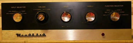
The schematic indicates that the tuner and aux I/Ps are functionally equivalent.
C20 and R33 form a bias network shared by all 4 O/P tubes. That requires all 4 EL84s to be closely matched. Switch to separate bias networks in each channel, which eases the matching criteria to pairs, instead of a quad. A 150 μF./50 WVDC cap. and 200 Ω/5 W. resistor in each network will do nicely enough. Part of your bass woes may be related to too small a cap. in the bias network.
The least expensive replacement O/P tube, with decent sonics, is the Russian 6П14П-EВ (6p14p-ev), AKA EL84M. Talk to Jim McShane for tubes and parts. BTW the "Russky" is tough as nails.
If you have not yet ordered replacements for the 4X 0.05 μF. coupling caps. (C19, C20, C44, & C45), buy 0.1 μF./400 WVDC 716P series Orange Drops. Again, it's a matter of bass performance.
Tone controls are a can of worms. Surprisingly few recordings benefit from their presence. My advice is to eliminate the tone controls.
RCA female spacing on "vintage" units is too close for use with modern interconnects. There is a way to completely replace the jack set, but that can wait for better fiscal times. For now, terminate the cables from the CDP, at the amp end, with affordable, Gold plated, Neutrik NYS352G metal barrel plugs, which fit into very tight spaces.
Eli, thanks so much for the info.......Could you clarify a couple things possibly?
1. I ordered some parts just prior to your response, so the 4 x .05uf orange drops are what I have on order......Would the .1uf help tighten the bass or increase the bass?
2. regarding separating the bias section into 2 parts. I like the idea.
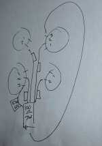
the makeshift diagram below, is what is there now (4 x 470k coming from each pin2 and 1 x 47uf from a pin 3, all going to one end of a 100ohm/7W and returning out the other end to a pin 3 of opposite el34 pair......Not sure how I'd separate the pair with your suggested 150uf/50v and 200 ohm/5w
Would each pair get that setup sounds like?
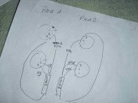
Not sure how to go about that?? the 2nd diagram?
1. I ordered some parts just prior to your response, so the 4 x .05uf orange drops are what I have on order......Would the .1uf help tighten the bass or increase the bass?
2. regarding separating the bias section into 2 parts. I like the idea.
the makeshift diagram below, is what is there now (4 x 470k coming from each pin2 and 1 x 47uf from a pin 3, all going to one end of a 100ohm/7W and returning out the other end to a pin 3 of opposite el34 pair......Not sure how I'd separate the pair with your suggested 150uf/50v and 200 ohm/5w
Would each pair get that setup sounds like?
Not sure how to go about that?? the 2nd diagram?
Attachments
Last edited:
If I remember correctly, the UA-1 and UA-2 use the same circuit without tone controls.
Best from Tucson
Bob
Best from Tucson
Bob
2. regarding separating the bias section into 2 parts.
Look at the schematic again. Discard the wire between the 2nd set of EL84s and the existing bias network. Replace the existing bias network with 1 set of parts of the new values. Install another bias network of the new values at the 2nd set of EL84s between the junction of the 2X pin #3 and the junction of the 2X 470 KOhm resistors. The 2 channels look alike.
Resistor/cap. combos, like those being discussed, form high pass filters. Experience shows that the 3 dB. down point of these poles should be at least 2 octaves away from the lowest freq. of interest, which is 20 Hz. The pairing of 200 Ω and 150 μF. "corner" at 5.3 Hz., which is marginal. OTOH, 470 KOhms and 0.047 μF. (the value of the Orange Drops you will receive) "corner" at 7.2 Hz., which is unacceptable. Make arrangements to swap the 0.047 μF. parts for 0.1 μF. parts.
Less is more, when it comes to NFB error correction signals. Correcting the cap. values reduces the deep bass error correction signal and bass tightness increases.
The least expensive replacement O/P tube, with decent sonics, is the Russian 6П14П-EВ (6p14p-ev), AKA EL84M. Talk to Jim McShane for tubes and parts. BTW the "Russky" is tough as nails.
Eli's right, the NOS Russians are a real good tube for you, they'll last and they are inexpensive.
If you have not yet ordered replacements for the 4X 0.05 μF. coupling caps. (C19, C20, C44, & C45), buy 0.1 μF./400 WVDC 716P series Orange Drops. Again, it's a matter of bass performance.
I see you already have some caps coming - maybe you can change the order to .1 caps. If you get stuck with the .047s I'll swap you for some .1s.
Drop a note if you need more details.
thanks for the offer....I found some .1 mallory's in my scraps and put them in, along with the new 200ohm/150uf bias.....I wasn't able to understand and figure how to separate into 2, so I assume the above values still are appropiate in the 'all 4 tubes biased the same' scenario......I still am trying to get a matched quad together to audition the changes and ultimately whether to decide on throwing the amp off the balcony and going back to solid state......I just want to listen to music and am not interested in an honerary EE degree. I wish a sub-$500 SS amp could get the 'tube' midrange sound. Because frankly, the low and high end of SS is fine with me.
lots of info on separating the bias and tone controls here. Note that the thread is for the AA-151. AFAIK they are the same, but the SA2 uses 12v line and phono tubes, where the 151 uses 6v. Other minor differences may linger.
I'm in the process of striping down my 151 and building it back up. Since these amps were built by hobbyists, I found all kinds of "interesting" work. Frankly, I'm surprised the amp didn't burn the house down. Also, nearly all the resistors and caps had drifted massively. The chassis isn't ventilated very well, and gets quite hot making it tough on components, especially 40yr old components.
In the end, it's costing me about 2x what I paid for the amp originally, which is ok. The price that most of these go for is what a set of power and output iron would go for. But getting things right on a tight budget might be frustrating.
I have the AA-151 also. I use a super quiet fan in the back and can run it all day and it never gets warm, without it I think it would burn itself up.
You may want to do the same thing with the SA-2. Good luck with your amp, heath kits are amazingly good
You may want to do the same thing with the SA-2. Good luck with your amp, heath kits are amazingly good
I wasn't able to understand and figure how to separate into 2, so I assume the above values still are appropiate in the 'all 4 tubes biased the same' scenario.
Using a seperate bias network for each tube has its advocates. IMO, that overlooks the fact that well matched tubes have slight differences, which are likely to increase over time. Having each PP pair share a bias network compensates for the minor differences between tubes.
Let's see if I can narrate what is necessary. For each PP pair, a wire connects between pin 3 of each socket. Connect the + terminal of the 150 μF. 'lytic to 1 of the pair's pin 3. Connect the - terminal of the cap. to the signal ground bus. Connect the 200 Ω resistor between the pair's 2nd pin 3 and the signal ground bus. Both of the PP pair's 470 KOhm resistors connect to the signal ground bus too.
Speaking of those 470 KOhm resistors, they should be replaced by 1% tolerance metal film parts. Noise is reduced and accuracy of the high pass pole "corner" freq. is increased.
- Status
- Not open for further replies.
- Home
- Amplifiers
- Tubes / Valves
- Need guidance with heathkit SA-2 refurbish/mods