I need bias voltage of 2.2 - 2.5v so according to the threads I should pick a green LED and the orientation I've seen in schematics have the - leg on the cathode and + on ground (which seems weird).
I am only using 1/2 of the tube and its transformer output in a very simple linestage.
So if I remove the cathode bias cap/resistor and just put in the green LED as outlined above it will work? I need between 11-13 mA of bias current. Right now a 222 Ohm resistor provides that.
I am only using 1/2 of the tube and its transformer output in a very simple linestage.
So if I remove the cathode bias cap/resistor and just put in the green LED as outlined above it will work? I need between 11-13 mA of bias current. Right now a 222 Ohm resistor provides that.
Sounds about right. You may want to test polarity with a batery and resistor. I have on several occasion gotten it backwards after cutting the leads of to fit the component.
Not all Green LEDS are created equal so you may have to try a few different ones. You can measure the potential it will regulate at by putting a 600R - 1k resistor in series with a 9volt battery. Then measure the potential across the LED.
Not all Green LEDS are created equal so you may have to try a few different ones. You can measure the potential it will regulate at by putting a 600R - 1k resistor in series with a 9volt battery. Then measure the potential across the LED.
Great! That's also what I was searching for is a way to easily measure them before just slugging them in.
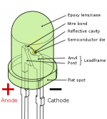
What I've read is the longer leg is positive. If you forget or cut the leads the larger section within the LED is the negative.
Running to a surplus store today so I was hoping to get a answer before I went. In the threads I've read here they said to get the 'dimmest' LED possible as they will have the lowest resistance.
Phrarod, the longer led is indeed the anode (+). It should go to the tube cathode. Often times the underside of the led body is flattened at the cathode (-) which can help when the leads are cut.
BTW, did you know: if you forget the series resistor on a red led, you get an orange led. No kidding!")
Kenneth
BTW, did you know: if you forget the series resistor on a red led, you get an orange led. No kidding!
Kenneth
LED and the orientation I've seen in schematics have the - leg on the cathode and + on ground (which seems weird).
To be clear, it goes this way.
Attachments
Diode - Wikipedia, the free encyclopedia
If you want diode to conduct in forward direction you'll have top connect anode to positive and cathode to negative supply, just like kavermei told you and just like what dsavitsk's picture shows. This is just like vacuum tubes, nothing to be confused about here
If you want diode to conduct in forward direction you'll have top connect anode to positive and cathode to negative supply, just like kavermei told you and just like what dsavitsk's picture shows. This is just like vacuum tubes, nothing to be confused about here
One more hint- the cathode (the part that's connected to ground) often has a small flat spot (sometimes pretty subtle) in the plastic molding. For the LEDs I've been using, the flat spot is on the tiny rim around the base of the device. Rectangular LEDs will sometimes have a chamfer.
Indeed they do when you look close enough. I intially could not see or feel them but with my 3x glasses I could. I had ASSUMED that they removed them on these new smaller LED's.
Hopefully now my propensity to get them in backwards will be reduced.
Thanks.
P.S. I never play the lottery for the same reason.
Hopefully now my propensity to get them in backwards will be reduced.
Thanks.
P.S. I never play the lottery for the same reason.
I my recently purchased batch of LEDs, the flat is actually parallel to the internal structure of the LED. The distance from each pin to the flat is the same... I guess both pins must be cathodes... Silly me. Of course not. Thankfully, the short pin is the cathode (-).
I've seen LEDs without any markings (flats, chamfers, etc.) on the body. But they've always had a long and a short pin. I don't think I've ever come across an LED where the short pin was not the cathode.
Surf mount LEDs are a completely different story, of course.
~Tom
Silly me. Of course not. Thankfully, the short pin is the cathode (-).I've seen LEDs without any markings (flats, chamfers, etc.) on the body. But they've always had a long and a short pin. I don't think I've ever come across an LED where the short pin was not the cathode.
Surf mount LEDs are a completely different story, of course.
~Tom
Hopefully now my propensity to get them in backwards will be reduced.
When in doubt, just hook them up with a 9V battery and 470R-1K resistor in series. It won't harm the LED if you get it wrong and you'll know when you get it right (it will light up). Whichever side goes to battery + when it lights up is obviously the anode.
If you can see inside the LED, the flying lead is usually + and the die body -.
Following on from what The Gimp has pointed out, if I look into an led from the side the cathode forms most of the bridge towards the anode in a sort of " r " shape, the anode being a sort of " 1 " shape.
Green LEDs turn yellow at around 105C case temp
That's to help you see them through the magic smoke
Last edited:
I connect them wrong now and again
I usually go by the flat on the case being the line on the symbol ie the cathode, same with normal diodes-line=cathode.
Some of the hyper mega super ultra bright types have the internals the other way round, also some infra-red types do too. I dought if you would need a super bright type for LED bias because the resistance is quite high but if your into radio they make good varactor diodes.
- Status
- This old topic is closed. If you want to reopen this topic, contact a moderator using the "Report Post" button.
- Home
- Amplifiers
- Tubes / Valves
- Need confirmation on LED bias for circuit