Hi there,
I have two 8 inch woofers from ADS L500 speakers that have no tweeters. Part number 206-0316.
Here are the parameters I measured, average of two drivers:
Znom: 4 ohm
Re: 3.0 ohm
Fs: 22.5Hz
Qms: 1.95
Qes: 0.33
Qts: 0.282
Sd: 211 sq.cm - approx
Vas: 50.5 liters
BL: 9 N/A
SPL: 84.4dB/W/m
I've been wanting to build a TL for a long time now and have not gotten around to it. These drivers would have the following TL alignement, according to the MJK fashion:
L = 147 inches
SL/SO = 1 (what I chose for simplicity and better ripple response despite low-Qts that might call for expanding line)
Xsectional area: 32.5 sq.inches
Driver offset would be about 43 inches
Although the line lenght is insane, the tiny Xsection makes it manageable in a double-fold enclosure of 48 inches high. Xsection would be 8 inches wide and 4 inches deep. I would end-up with external dimensions of 48 inches high by 15 inches deep by 9.5 inches wide, not bad. Fits in two 4'x8' sheets of 3/4 ply.
And although it does not pertain to my question, that would be a 2-way design, with a soft-dome tweeter.
How does that sound?
IG
Last edited:
Why don't you ask MJK?
Visit Quarter Wavelength Loudspeaker Design to gain access to the QW forum. He visits the forum frequently to help folks just like you.
Visit Quarter Wavelength Loudspeaker Design to gain access to the QW forum. He visits the forum frequently to help folks just like you.
Why don't you ask MJK?
Visit Quarter Wavelength Loudspeaker Design to gain access to the QW forum. He visits the forum frequently to help folks just like you.
I'm not currently a member over there and I know there's many knowledgeable folks around these parts too, so I thought I'd post here for now.
My main concern is about the driver's parameters, which are quite unusual, with very low Fs and low Qts. I have never attempted a DIY project with something like that and have never read about projects that employed similar drivers. This is a perfect driver for a sealed enclosure, which is what the ADS L500 is, but the resulting TL geometry is a very long and very thin line. I wonder what are the inherent issues here, cause I'm certain there's gotta be some.
And about the driver; in it's sealed enclosure it starts rolling-off way above it's Fs, probably around 50-60 Hz, but the calculated TL would attempt to use it down to it's Fs, unless I tune it a bit higher, which I probably should, say around 35Hz. The low Qts also suggests that this may be a wise thing to do.
Well, I'll see if I get the advice I need here first! 🙂
IG
Good luck with getting good advice here.
Keep in mind that TL"s aren't known for for their low freq. extension. Folks like them because of their sound. The biggest challenge with TL's is taming the response ripples.
Keep in mind that TL"s aren't known for for their low freq. extension. Folks like them because of their sound. The biggest challenge with TL's is taming the response ripples.
Hi IG81,
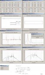
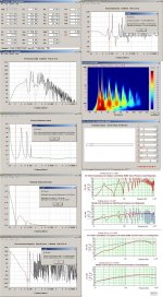
Try learn HR (Horn-response) but I advise you to take a step-by step approach when using the program for a TL design (no stuffing is used) = OD or Nd in HR.
See the plots in my submitted pictures that for the very last pictures and plots
show an identical airways un-stuffed/stuffed MJK FR plots to compare with.
IMO: Its clear that your TL = straight QWP design lack a low f-3dB point when just by calculating your driver in box seen equivalent Qt value ( depending of the closed pipe volume).
b🙂
Attachments
The driver's specs are suited for B%$3 WC, TH or similar loading, but I assume don't have enough Xmax for acceptable performance anywhere near its Fs.
The long, tiny pipe will compression load the driver, reducing its effective Qts, further over-damping them. It won't make for an accurate reproducer, but it will be very 'tight'/'fast'. A max flat impedance TL OTOH will work well, though will have a much higher tuning same as a T/S max flat vented alignment (22.5/0.282 = ~79.8 Hz), but a much slower roll off, so much more accurate with ~transient perfect response.
Driving these with a high output impedance will raise its effective Qts which will in turn increase the net pipe volume required, lowering its compression loading, max flat impedance tuning.
WRT choosing a TL alignment with a Qts < ~0.4, calculating a T/S max flat alignment to get an acceptable cross sectional area (CSA), tuning has worked well enough for me, but I did these long before MJK's work, so tend to be larger in the few I've compared, though should still be fine for choosing a tuning (~32 Hz for this driver). For > ~0.4 Qts, I use a max flat impedance alignment.
GM
Google for George Augspurger's article, I think in the old Voice Coil magazine. He also had a software he wrote, probably the best TL calculator to date.
Study the question of stuffing a lot. Rock wool is good but settles over time; I think the chunk-y fiberglass may be better. And of course, bends can reduce some end-to-end reflections, but sharp bends are hard on proper operation.
I do think your unusual parameters seem like good candidates for a TL. Good luck!
...George Augspurger's article, I think in the old Voice Coil magazine. He also had a software he wrote, probably the best TL calculator to date.
It has never been updated & is very limited in what it will calculate. MJK is better.
dave
Thanks for the info you guys!
Before I got to read your answers, I already calculated for a ~35Hz tuning. It would yield pretty much the same external box dimension, with a single fold this time, CSA increasing a bit this time.
I checked with the physical build with ¾ ply and would have the following geometry:
L = 89.5", yielding a theoritical 37.7Hz tuning
CSA = 8" by 6.5", 52sq.in
driver offset (0.349) = 31.35"
I think that would be a saner aproach. I'll try to look it up in HR, see what I can do. For now I seem to be unable to download HR, websites seem to be down or something.
Here's what it'd look like:

48" high, 15.25" deep, 10.5" wide. The side panels would sandwich all the other 8" wide front, back and interior baffles. Not show are corner 45deg braces and perhaps a few braces along the way to subdivide baffles into smaller sub-panels. I would initially stuff the first 2/3 of the line and experiment to suit my taste.
IG
Before I got to read your answers, I already calculated for a ~35Hz tuning. It would yield pretty much the same external box dimension, with a single fold this time, CSA increasing a bit this time.
I checked with the physical build with ¾ ply and would have the following geometry:
L = 89.5", yielding a theoritical 37.7Hz tuning
CSA = 8" by 6.5", 52sq.in
driver offset (0.349) = 31.35"
I think that would be a saner aproach. I'll try to look it up in HR, see what I can do. For now I seem to be unable to download HR, websites seem to be down or something.
Here's what it'd look like:
48" high, 15.25" deep, 10.5" wide. The side panels would sandwich all the other 8" wide front, back and interior baffles. Not show are corner 45deg braces and perhaps a few braces along the way to subdivide baffles into smaller sub-panels. I would initially stuff the first 2/3 of the line and experiment to suit my taste.
IG
Last edited:
Other than actual bracing, those 45-degree corner braces don't perform any function, certainly not any acoustical ones. They don't "direct" the sound waves around the bends as was believed eons ago; the wavelengths of the lower frequencies, which is what a TL is mostly about, are too long to even "see" the deflectors, and the higher frequencies will be absorbed by any stuffing installed in the line.
Paul
Paul
Thanks for the info you guys!
Before I got to read your answers, I already calculated for a ~35Hz tuning. It would yield pretty much the same external box dimension, with a single fold this time, CSA increasing a bit this time.
I checked with the physical build with ¾ ply and would have the following geometry:
L = 89.5", yielding a theoritical 37.7Hz tuning
CSA = 8" by 6.5", 52sq.in
driver offset (0.349) = 31.35"
I think that would be a saner aproach. I'll try to look it up in HR, see what I can do. For now I seem to be unable to download HR, websites seem to be down or something.
Here's what it'd look like:
View attachment 189817
48" high, 15.25" deep, 10.5" wide. The side panels would sandwich all the other 8" wide front, back and interior baffles. Not show are corner 45deg braces and perhaps a few braces along the way to subdivide baffles into smaller sub-panels. I would initially stuff the first 2/3 of the line and experiment to suit my taste.
IG
Other than actual bracing, those 45-degree corner braces don't perform any function, certainly not any acoustical ones. They don't "direct" the sound waves around the bends as was believed eons ago; the wavelengths of the lower frequencies, which is what a TL is mostly about, are too long to even "see" the deflectors, and the higher frequencies will be absorbed by any stuffing installed in the line.
Paul
Especially on the long line section in the back of the cab, wouldn't the 45deg corners help reduce standing waves by eliminating parallel surfaces?
Other than that, how does this last geometry look to you guys?
IG
Especially on the long line section in the back of the cab, wouldn't the 45deg corners help reduce standing waves by eliminating parallel surfaces?
Other than that, how does this last geometry look to you guys?
IG
Tapering the line will help mitigate the ripples. Upon closer examination of your drawing, I suggest you either shorten your vertical brace somewhat or put the woofer higher so there is a clear path for the woofer's back wave to travel down the line to the exit mouth. Slant the vertical wall so the line tapers going from top to bottom. Read up on this at Q-W.com.
Last edited:
Especially on the long line section in the back of the cab, wouldn't the 45deg corners help reduce standing waves by eliminating parallel surfaces?
Other than that, how does this last geometry look to you guys?
IG
Only where the reflectors are large WRT the WLs, so typically only affect the BW well above the cab's pass-band, ergo irrelevant since even minimal damping will quell them enough. Acoustically, tis better to leave them as is since the slight bulging of the corners act as a series of low pass filters to help roll off its upper pipe harmonics.
If it follows MJK's math, there's nothing fundamentally wrong with it, but a reverse taper works better IME for low Qts drivers since the stronger the motor, the more back pressure it want's to 'feel', so a shorter path-length for a given tuning is required if tapered.
GM
a reverse taper works better IME for low Qts drivers
By reverse taper you mean an expanding line going towards the open end? That's how I always understood it.
a shorter path-length for a given tuning is required if tapered.
GM
This bit confuses me here. While it makes sense, it's not what applies to my situation, where with an expanding line, a longer line should be required for the same tuning frequency, is that correct?
Thanks!
IG
By reverse taper you mean an expanding line going towards the open end? That's how I always understood it.
This bit confuses me here. While it makes sense, it's not what applies to my situation, where with an expanding line, a longer line should be required for the same tuning frequency, is that correct?
Thanks!
IG
Okay, so now you've gotten obviously conflicting and confusing advice. STRONGLY suggest you take the time and sign up at the Q-W forum and get answers to your questions you'll have more confidence in.
Tapering the line will help mitigate the ripples. Upon closer examination of your drawing, I suggest you either shorten your vertical brace somewhat or put the woofer higher so there is a clear path for the woofer's back wave to travel down the line to the exit mouth. Slant the vertical wall so the line tapers going from top to bottom. Read up on this at Q-W.com.
I did read a lot already on QW.com, but it's a lot to absorb. 🙂
I think I found what confuses me a bit.
1. On the one hand, a strong motor wants to feel more pressure, like a compression chamber in a horn, so a tapered line, with a smaller exit, sor of acts towards that goal by restricting the back wave.
2. But an expanding line will produce more output at the ¼-wave frequency, which won't be strong due to a low-Qts driver, so I always thought that would be recommended for such a situation, especially since such a geometry does look like a horn, albeit with no compression chamber.
IG
No, contracting, or what I choose to define as a TQWT. Expanding means a horn to me, so must be longer than either a TQWT or TL (straight taper) for a given tuning.
GM
GM
No, contracting, or what I choose to define as a TQWT. Expanding means a horn to me, so must be longer than either a TQWT or TL (straight taper) for a given tuning.
GM
Ok, I understand now. It's just that I often read of TQWT and Voigt pipes being lumped together.
Now at least I understand that both you and speaker doctor are pointing me toward the same thing! 🙂
A contracting line is more desirable for me, to have a smaller enclosure as well. I'll get working on this.
Thanks!
IG
Last edited:
Ok, I understand now. It's just that I often read of TQWT and Voigt pipes being lumped together.
Now at least I understand that both you and speaker doctor are pointing me toward the same thing! 🙂
A contracting line is more desirable for me, to have a smaller enclosure as well. I'll get working on this.
Thanks!
IG
Don't get all warm and fuzzy feeling yet about this.
The Asian culture has a great way of getting to the right answer by asking the same question of many different people. Still suggest you visit Q-W.....
Ask the same questions there and see how the QW experts respond.
Ok, I understand now. It's just that I often read of TQWT and Voigt pipes being lumped together.
A contracting line is more desirable for me, to have a smaller enclosure as well. I'll get working on this.
Thanks!
IG
TQWT ('tuned quarter wave tube' or 'tapered quarter wave tube' depending on who you ask, so already potentially confusing to the uneducated) is a much abused acronym that has been used to describe all forms of vented alignments that have a very high aspect ratio and why once these started begin having a bit of popularity among DIYers I chose to define them beyond their electrical equivalents which are all lumped together as TLs (transmission lines) in the hope of keeping confusion to a minimum. MJK's software rules though and he disagrees with me, so I guess when folks other than me use these acronyms the gentle reader won't know what type of TL they're talking about without further description.
The Voigt pipe OTOH can only be either a straight TL or expanding TL (horn) since there's no reverse tapered (TQWT) designs in his patent (see attached).
It takes 'x' amount of net box volume (Vb) for 'y' gain bad-width (BW), so regardless of the path-length, the net Vb needs to be ~the same for the same gain BW.
GM
Attachments
- Status
- Not open for further replies.
- Home
- Loudspeakers
- Multi-Way
- Need advice on a TL build