I mean something like this. Unfortunately the leakage spec of the BS250 is a bit high (and most other discrete PMOS transistors are worse): 0.5 uA maximum at 25 degrees C and 25 V. Chances are that the typical leakage current at 9 V or less is much smaller, but no-one guarantees that.
Attachments
Last edited:
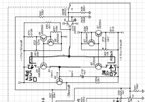
....nowhere do they tell you what the pot R8 is for....
Meter-trim, obviously.
However it seriously interacts with Release. And the noise-figure looks awful with the steep attenuator before a BiFET chip. It is not the CompLimiter I remember (but I can't be sure what I remember of those days).
There are better examples to study.
1176 Peak Limiter - Wikipedia
https://leachlegacy.ece.gatech.edu/papers/limiter.pdf
Fast Audio Peak Limiter
PWM Tremolo Experiment and audio clips
PWM Tremolo Experiment and audio clips
Blesser, B. and Ives, F. (1972). A reexamination of the S/N question for systems with time-varying gain or frequency response. Journal of Audio Engineering Society 20(8): 638-641.
Blesser, B. (1972). An ultraminiature console compression system with maximum user flexibility. Journal of Audio Engineering Society. 20(4): 297-302.
Blesser, B. (1969). Audio dynamic range compression for minimum perceived distortion. IEEE Transactions on Audio and Electroacoustics 17:22-32.
Bäder, K. and Blesser, B. (1968). Ein Kompressoren mit variablen Eigenshaften und Pulsedauermodulation. Radio Mentor Electronics, 9:33-34.
Blesser, B. and Kent, A. (1968) Analysis of a feedback-controlled limiter using a logarithmic measuring scale. IEEE Transaction of Audio and Electroacoustics 16:481-485.

Attachments
Last edited:
I mean something like this. Unfortunately the leakage spec of the BS250 is a bit high (and most other discrete PMOS transistors are worse): 0.5 uA maximum at 25 degrees C and 25 V. Chances are that the typical leakage current at 9 V or less is much smaller, but no-one guarantees that.
Thanks, I was actualy thinking of turning off the ccs also. Will look at some options. Not too familiar with Mosfets eithier. Maybe time to learn.
Also thinking about changing some criteria, like using a V reg or not using a battery at all. Would sure make things easier. Maybe even make it a rack-mount, I keep coming up with additional mods like in/out mix and sidechain filtering, all will use more power. Thanks again. These circuits are not the usual diyaudio amps, eqs, and buffers so I thought this might be an interesting change for some. Back to Ltspice.
Meter-trim, obviously.
However it seriously interacts with Release. And the noise-figure looks awful with the steep attenuator before a BiFET chip. It is not the CompLimiter I remember (but I can't be sure what I remember of those days).
There are better examples to study.
1176 Peak Limiter - Wikipedia
https://leachlegacy.ece.gatech.edu/papers/limiter.pdf
Fast Audio Peak Limiter
PWM Tremolo Experiment and audio clips
PWM Tremolo Experiment and audio clips
Blesser, B. and Ives, F. (1972). A reexamination of the S/N question for systems with time-varying gain or frequency response. Journal of Audio Engineering Society 20(8): 638-641.
Blesser, B. (1972). An ultraminiature console compression system with maximum user flexibility. Journal of Audio Engineering Society. 20(4): 297-302.
Blesser, B. (1969). Audio dynamic range compression for minimum perceived distortion. IEEE Transactions on Audio and Electroacoustics 17:22-32.
Bäder, K. and Blesser, B. (1968). Ein Kompressoren mit variablen Eigenshaften und Pulsedauermodulation. Radio Mentor Electronics, 9:33-34.
Blesser, B. and Kent, A. (1968) Analysis of a feedback-controlled limiter using a logarithmic measuring scale. IEEE Transaction of Audio and Electroacoustics 16:481-485.
Thank you. Those are mostly comps that use a fet as the variable gain stage, Im using a VCA. What I learned is it is possible to use a fet in its ohmic region by adjusting the gate drive with a pot. 2 of those comps do that so Im assuming its reasonable, and dosnt drift too much.
Last edited:
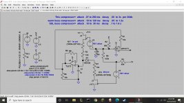
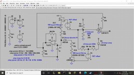
These other fet circuits have made me rethink this and Im trying to trim out the offsets. Heres the circuit with some offsets and trimmers to adjust them. The sim works fine but Im wondering if Im missing something that will cause grief with the real fets. The one thing I see is the need for a V reg. A 1volt drop in V+ changes the TCs up to 50%. Not acceptable.
Attachments
Do you expect anything to go wrong if the JFETs turn off more gradually in reality than in the simulation? If so, have you checked the drain current versus the gate-source voltage near pinch-off, with a constant VDS of a few volts?
Ild expect them to burn a bit of extra power but nothing serious, theres a 10k R between the 2 fets? Is that sentence about testing the spice model?
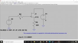

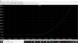
As you use them at microamp current levels, could you look at the part between 26.4 ms and 26.9 ms and either make the current scale logarithmic or zoom in to the part between 0 and 10 uA?
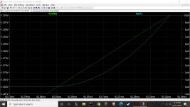
It's a simple quadratic model that is very inaccurate at the low current levels where you want to use the JFETs, but it could be that that just means that your circuit behaves better in reality than in simulations.
For low currents, the curves of the real-life JFET will be much smoother than what you get out of your simulator. As a rough approximation, imagine the part below 28 uA is replaced with an exponential voltage dependence where each 60 mV decrease of VGS causes the current to drop by a factor of ten.
As a result, the charging and discharging time constants will change more gradually than simulated as a function of the gate-source voltages. That could very well be an advantage.
So finding the sweet spot with the Vg adjust pot might be easier? At this point looks like its time to try the real circuit.

I'm no expert and barely even a novice at circuits, but I found this:
"The LT1357 is a high speed, very high slew rate operational amplifier with outstanding AC and DC performance. The LT1357 has much lower supply current, lower input offset voltage, lower input bias current, and higher DC gain than devices with comparable bandwidth."
..but that's for an opamp.
Perhaps look up fast slew rate FETs? JFET or MosFET? hmm.
I think slew rate is important for what you want to do and hope it has a very low noise floor. like maybe 18-24V supply voltage instead of the typical 9V and use a high quality 1:1 Hi-Z isolation audio transformer before the FET circuit.
edit: noob here. I didn't realize to click past page 1 before replying. sorry ^^;
Last edited:
Heres the circuit I will build. The bias adjust seems to work for Vps out as much as 3 volts and not too finicky ( a 5% change in the pots from the bias point dosnt change much ) . The temperature comp diode for J2 seems to help but not sure if spice is lying or not.
Attachments
Last edited:
.
For low currents, the curves of the real-life JFET will be much smoother than what you get out of your simulator. As a rough approximation, imagine the part below 28 uA is replaced with an exponential voltage dependence where each 60 mV decrease of VGS causes the current to drop by a factor of ten.
Marcel, 60mV/decade is the theoretical maximum subthreshold conduction slope for MOSFETs. For JFETs, the slope is much lower, usually under 20mV/decade. It is also strongly temperature dependent, which makes it totally impractical to characterize JFETs in that region. It is fair to say, JFETs should not be used close to the threshold/pinch gate voltage, the results are impredictible.
I'm no device physicist and certainly no JFET expert, like I wrote in post #3. I know JFETs have an exponential region because Peter Baxandall mentioned it in an article from many decades ago, so I just assumed it to be similar to a MOSFET in weak inversion, but without the voltage division between the oxide capacitance and a junction capacitance that you have in MOSFETs. (In a normal bulk MOSFET, you only get 60 mV/decade at room temperature when you drive both the gate and the bulk.)
If you are right, that means JFETs can have three times the transconductance of bipolar transistors at low currents. I always thought the transconductance to current ratio of a bipolar transistor was some physical limit.
If you are right, that means JFETs can have three times the transconductance of bipolar transistors at low currents. I always thought the transconductance to current ratio of a bipolar transistor was some physical limit.
Transconductance in a bjt is approx q/kT * Ic (S ~ 40*Ic), in a jfet fixed according to specs. At very low currents the transconductance of a jfet can have a higher value then a a bjt at the same current. But at Vgs < 0.8*Vpo or Vbe > 0.4V this does not apply anymore.
- Home
- Source & Line
- Analog Line Level
- Need advice from JFET expert