All true, JFET may have a higher transconductance in the subthreshold region, compared to a BJT at the same current.
Marcel, 60mV/decade is the theoretical maximum subthreshold conduction slope for MOSFETs. For JFETs, the slope is much lower, usually under 20mV/decade. It is also strongly temperature dependent, which makes it totally impractical to characterize JFETs in that region. It is fair to say, JFETs should not be used close to the threshold/pinch gate voltage, the results are impredictible.
I had no problems using JFET's like 2SK222 at 10uA in a microphone in fact there was almost no audible difference to them running at 1mA.
Not sure what that all means for the circuit I designed. Am I asking too much from the FETs, a relatively stable resistance ( a 10% chage is tolerable) that I can adjust from 100k to 12M ohms? At 5 volts thats only .5 ua. Well I already bought the FETs so its time to play. Will update after testing, which may take some time to figure out. Is there anything in particular you guys want me to measure? (if my limited test gears up to it).
Last edited:
You're asking for a lot. A JFET at 12M in the triode region is probably in deep sub-threshold and tracking over 2 orders of magnitude within 10% might be a problem.
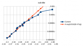
Made curious by post #39, I took a BF247A and a bunch of resistors from the attic, connected each resistor in turn between source and gate and connected a 9 V battery (with 8.87 V Thevenin voltage) in series with a multimeter between drain and gate. I used an IC socket to swap the resistors without heating up the JFET. I also did some measurements with the 1 Mohm multimeter in parallel with the resistor. Weak points of my measurements are that the drain-source voltage gets slightly larger at the higher drain currents, that the meter is a cheap old Topcraft TDM600 and that the resistors had 5 % tolerance, the highest three values even 10 %.
The result seems to fit best with an exponential with kT/q multiplied by about a factor of 1.5, so about two thirds of the transconductance of a bipolar transistor. The meter has a resolution of 100 nA, so for currents below 2 uA I put it in the 200 mV voltage range and connected a 100 kohm resistor in parallel (measured to be 100.2 kohm, the input resistance of the meter itself was still 1 Mohm nominal).
The result seems to fit best with an exponential with kT/q multiplied by about a factor of 1.5, so about two thirds of the transconductance of a bipolar transistor. The meter has a resolution of 100 nA, so for currents below 2 uA I put it in the 200 mV voltage range and connected a 100 kohm resistor in parallel (measured to be 100.2 kohm, the input resistance of the meter itself was still 1 Mohm nominal).
Attachments
Not sure what that all means for the circuit I designed.
Basically that we don't know exactly how finicky the settings will be.
Am I asking too much from the FETs, a relatively stable resistance ( a 10% chage is tolerable) that I can adjust from 100k to 12M ohms? At 5 volts thats only .5 ua. Well I already bought the FETs so its time to play. Will update after testing, which may take some time to figure out. Is there anything in particular you guys want me to measure? (if my limited test gears up to it).
10 % change under what conditions? It will change with temperature, but when you set your compressor to a setting you like by listening to it and after that the temperature stays nearly constant, that may not be an issue. It may be a different matter when you need the same setting to work perfectly no matter whether it freezes or it's very hot.
Last edited:
That graph is promising. I guess 10% drift from anything. Probably mostly temperature. Ild also not expect it to be used at the outside limits very often, which might help reduce the drift.
Last edited:
I had no problems using JFET's like 2SK222 at 10uA in a microphone in fact there was almost no audible difference to them running at 1mA.
The temperature dependence must be brutal, although for a microphone application it may not matter.
At what point is the temp dependance the worse, close to Vp? Any way Ill try to use the .5 to 50 uA range (gives the TCs Im looking for) about a volt from Vp, and test the temp stability.
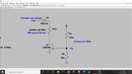
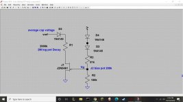
Did some temperature dependence testing with this circuit.
Vg=6v, Vref=4.5v
I set Id to 1uA with the 2M pot at 62F then changed the temp.
40F .99uA, 100F 1.04uA, 120F 1.05uA
So about 6% over 80 degrees F. Also did a quick test at Id=10uA which gave similar results. The diodes are working better than I expected.
Vg=6v, Vref=4.5v
I set Id to 1uA with the 2M pot at 62F then changed the temp.
40F .99uA, 100F 1.04uA, 120F 1.05uA
So about 6% over 80 degrees F. Also did a quick test at Id=10uA which gave similar results. The diodes are working better than I expected.
Attachments
- Home
- Source & Line
- Analog Line Level
- Need advice from JFET expert