Hi Summer,
in reality I didn't pay attention to the OT transformer, being the other french guy to deal with it.
Apparently the OT seeems to have a U.L. tap but "phisically" I don't know, I have to ask if it has two B+ separate windings (as multi-impedance). I know a quite high ratio was wished as option to reach, for minimized distortion reasons.
Xmas is here and Santa is bringing one of these Oldchen amp home. Here is the list of things I have planned:
Other things that I am forgetting?
- Add grid stoppers to all tubes, kind of 1K to 3K
- Add B+ bleeder, ~330K/2-3W
- Change the first B+ filter cap to plastic 20uF to save the 5U4 from premature death
- Rewire the whole HT loop from TR secondary to rectifier to first filter cap to twisted wire, located right on the central axis of the chassis (as far away from the driver tube as possible)
- Ground trafo HT center tap through a fuse
- Tightly twist filament cables, if not already
- Star-connect B+ and heater power, separate cabling per channel
- Possibly add extra 47-100R and 270uF RC network on each channel's B+ to isolate them - needs auditioning
- Place the power switch at the back or side panel, close to the IEC and away from the driver tube
- Change o/p to pseudo-triode mode, at reduced max o/p power of course, but I don't care for the UL sound
- Remove feedback, no need or want when in pseudotriode mode
- Revisit driver topology - I always go for PSE, no cascode, SRPP or two-stage cascade. This should easily drive the EL34 Miller capacitance
- Bypass cathode resistor to reduce driver rp & distortion
- Check and modify operating point if required to run the drivers hot
- Nevermind the reduced gain, I have all the gain I need
- B+ would be on the low side, but check if the EL34 operating point is hot enough. A 5V4G is at hand as well.
- Change coupling caps to Mundorf, I have some spares, various types
- No need for a volume pot for me, will remove
- Input signal routing and type to be improved to VDH. Input signal connectors best located close to drivers, but not very convinient - will check
Other things that I am forgetting?
Last edited:
Check the quality of the RCA connectors on your stock amplifier. On mine the bulk metal was iron, plated with a yellow "gold" coating. I replaced them with better quality ones. I was unable to hear a difference after the upgrade but those budget RCA connectors are prone to oxidation after only a few years. The 5H choke is below the right output transformer and shares a mounting screw with it. On my amplifier there is a slight hum on that channel due to magnetic coupling after the removal of the global feedback connection. In the future I will remove the choke and replace it with a RC combination. The original power switch looked a bit sketchy and had no UL or CE labels on it. I replaced it with a safe one.
Having received the amp a few days ago, I spent some time on it. Mine came with 6SN7s, schematic very close to that YamaA700 posted, with the 6SN7 sections unfortunately wired in cascode. I of course swapped the first HT smoothing cap of 100uF with the 22uF of the first stage B+ filter cap before I powered it up:

B+ on the EL34s is only 273V, and it needs to be raised by an extra helper transformer. Filament voltages are OK at 6.13V and 4.8V, with my mains voltage being 6.5% lower than nominal. B+ on the driver stage is 252V, again quite lower than ideal, as the upper 6SN7 section sees 90V across it, and the lower one a whopping 44VDC. The poor thing only has 1.6mA running through it and needing to drive the EL34 Miller capacitance.
Strangely enough there are no visible signs of instability with a nasty 8R/47nF load, despite the uncompensated structure. Here is the 1KHz squarewave (blue in, yellow out):

No other capacitor value seemed to bother it. In any case, I am not connecting my beloved speakers to it without at least adding the grid stoppers first. So, no listening tests yet.
Closed-loop gain measures 25dB, 3dB small-signal BW is 9.5Hz to 41KHz. Feedback amounts to 5.3dB.
Distortion:

Opening the loop yields as expected from the feedback factor about half the small-signal BW, 19Hz to 23KHz. Not bad material for the price, the top end will hopefully be extended by improving the driver stage.
Despite being neatly arranged, the wiring is electrically very suboptimal, the left channel feedback wire being tied together with the HT ac wires, thus picking up severe amounts of mains and 2x hum:

That is the reason why the left channel hums more than the other one, not the choke or the smoothing cap value or anything else. The amount of hum is of course volume setting dependent as the garbage pickup gets shunted by the pot. Simply moving the 2K feedback resistor from the binding post to the input tube grid lead improves this significantly, but I plan to neither have feedback nor keep the same wire routing. Not even the heater wiring is twisted, so it radiates as mad. The grounding wiring is also suboptimal in several locations.
The right channel is in (a bit) better shape:

Basically the whole thing needs rewiring, and the topology many changes in my view. So that is only the beginning🙂
B+ on the EL34s is only 273V, and it needs to be raised by an extra helper transformer. Filament voltages are OK at 6.13V and 4.8V, with my mains voltage being 6.5% lower than nominal. B+ on the driver stage is 252V, again quite lower than ideal, as the upper 6SN7 section sees 90V across it, and the lower one a whopping 44VDC. The poor thing only has 1.6mA running through it and needing to drive the EL34 Miller capacitance.
Strangely enough there are no visible signs of instability with a nasty 8R/47nF load, despite the uncompensated structure. Here is the 1KHz squarewave (blue in, yellow out):
No other capacitor value seemed to bother it. In any case, I am not connecting my beloved speakers to it without at least adding the grid stoppers first. So, no listening tests yet.
Closed-loop gain measures 25dB, 3dB small-signal BW is 9.5Hz to 41KHz. Feedback amounts to 5.3dB.
Distortion:
Opening the loop yields as expected from the feedback factor about half the small-signal BW, 19Hz to 23KHz. Not bad material for the price, the top end will hopefully be extended by improving the driver stage.
Despite being neatly arranged, the wiring is electrically very suboptimal, the left channel feedback wire being tied together with the HT ac wires, thus picking up severe amounts of mains and 2x hum:
That is the reason why the left channel hums more than the other one, not the choke or the smoothing cap value or anything else. The amount of hum is of course volume setting dependent as the garbage pickup gets shunted by the pot. Simply moving the 2K feedback resistor from the binding post to the input tube grid lead improves this significantly, but I plan to neither have feedback nor keep the same wire routing. Not even the heater wiring is twisted, so it radiates as mad. The grounding wiring is also suboptimal in several locations.
The right channel is in (a bit) better shape:
Basically the whole thing needs rewiring, and the topology many changes in my view. So that is only the beginning🙂
Last edited:
Amplifier noise spectrum, factory state, left channel:

Amplifier noise spectrum, after rewiring and mods, left channel:

Mains hum and buzz are down by some 40+ dB. In fact, what remains in the plot is measurement system hum residue. I think this qualifies as an improvement.
Mods list:
This is fresh out of the soldering work - I will post some measurements and maybe a listening comment or two.

Amplifier noise spectrum, after rewiring and mods, left channel:
Mains hum and buzz are down by some 40+ dB. In fact, what remains in the plot is measurement system hum residue. I think this qualifies as an improvement.
Mods list:
- Rewired everything from the ground up - all components were first removed, the strip board and horrible silicone cleaned. Heater wiring is tightly twisted. The seriously messed up factory grounding scheme was fixed.
- Changed o/p stage to pseudo-triode mode
- Fixed the ill-conceived operating points of both 6SN7 sections by increasing the idle current to 4mA and redefining the anode voltages
- Removed the ill-conceived upper tube anode / lower tube cathode connection of the cascode grid voltage divider. Absolutely no benefit from it in simulations.
- Increased B+ via extra 2x15V transformer - needs 2x35V and possibly higher voltage B+ cap
- Added grid stoppers
- Removed feedback
- Designed for an overall gain of ~23dB
- Improved component quality
- Split B+ RC filters towards 6SN7s per channel
- Heatshrink now protects transformed wiring from chassis entrance holes
- Created a virtual center tap to reference to ground the EL34 filaments
This is fresh out of the soldering work - I will post some measurements and maybe a listening comment or two.
Last edited:

@hollow_man For points 2 and 3: Did you keep the cascode driver cicuit? If so, could you post a schematic with the component values you've implemented? My version came with the schematic as in post #1, but I'm thinking of rewiring this.
@arjen6t8 here is the modded schematic:

However, I have now changed to a classic DC-coupled cascade (not cascode), because I wasn't very impressed with the cascode sound. It is an idea that I haven't seen to be practiced by high-end tube manufacturers - at least those whose sound signature I like, like Canary Audio, Octave, etc.
If you think about it, who gets a very happy sounding 6NS7 to try to mimic a pentode with it?
Frankly, don't waste your time with the pseudo-pentode bussiness IMHO. I would call it unlistenable. This one sounds vastly superior straight out of the box:

It even has more gain than the pathetic factory implementation for those who want to experiment with feedback 🙂
Here's the distortion: It really needs a higher B+ though:

1W noise and distortion spectra:

Frequency response into 8R:

-3dB @ 16.1Hz, upper corner limited by antialias filter.
It so happens that countless serious manufacturers, e.g. Audio Research, have used the cascade in many products. Not one have I seen employing the pathetic pseudo-pentode idea.
It even has more gain than the pathetic factory implementation for those who want to experiment with feedback 🙂
Here's the distortion: It really needs a higher B+ though:
1W noise and distortion spectra:
Frequency response into 8R:
-3dB @ 16.1Hz, upper corner limited by antialias filter.
It so happens that countless serious manufacturers, e.g. Audio Research, have used the cascade in many products. Not one have I seen employing the pathetic pseudo-pentode idea.
Last edited:
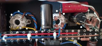
Couple of pictures:

The two 100R resistors create the virtual center tap to reference the EL34 filaments to ground. The cathode would also be another possible reference point.
The copper bar can also be seen. Grounds are star-connected per tube. So is B+.
The second triode section grid stopper filts nicely closest to the socket.
I had a foil cap for coupling and used that, but something better would be nice. The cathode bypasses also need better parts.
I have some real NOS 6SN7s, but I am not getting into tube rolling until I get it to sing first. Also, the feedback/no FB trial will be the last one.
Next is increasing B+ so that some more power can be had, altough I am happy with the 3-4W watts I currenty get from it.
Thanks! Mine came as a kit that I built a few years ago. I had followed all good practices, but it had hum on one channel. I tried relocating the choke, running the heaters of the triodes from DC and some other things, but I could not get rid of the hum. Seeing this thread made me take it out of the cupboard again. I checked one of the OPT's, that had an airgap OK. I will check the other one as well, and probably rebuild completely.
If you want a higher B+, you can always substitute the choke for a capacitor multiplier, or get rid of the tube rectification altogether and go solid state there.
If you want a higher B+, you can always substitute the choke for a capacitor multiplier, or get rid of the tube rectification altogether and go solid state there.
All same amp owners: check that the RCA grounds are connected to circuit ground. In mine they weren't, believe it or not! The input signal return path was thus through the mains earth - a very bad idea.
I am finished with the bulk of the "changes". A picture first and then a summary:


(To the left my push-pull triode-strapped EL84 amp). Sorry Oldchen for your logo but that was no place to print it.

Measured voltages are very close to those indicated by LTSpice.
The 8K06 B+ isolating resistor needs to be that high otherwise the two stages interact at low frequencies where the RC network does not isolate enough.
The lead network is a placeholder for when the FB experiment will be made (if ever). The cap strating value should be 150p in that case. Same goes for the feedback resistor which can be 18K for 5.5dB of feedback.
Output power is plenty enough for me. Measured distortion is:


Also, mains hum is all but obliterated. What is shown here is a measurement artifact. No need for DC on the filaments.
3dB 1W power bandwidth is 8.5Hz to 43KHz.

Yellow and blue traces are input vs output 1KHz signal. Can you tell which one is which?😉
And yes, it sounds fantastic by any high-end standard (to me), and no, the sound bears no resemblance whatsoever to that of the factory unit.
I am finished with the bulk of the "changes". A picture first and then a summary:
- The black toroid is a 2x45V one. This coupled with a change of the stock 5U4G to a Sylvania 5V4G increase B+ from 300V to 350V, where I want it to be. This makes for an anode voltage (after the cathode voltage drop) of 300V. The rectifier filament voltage is also happier now at 5.02V from 4.6V, as the 5V4 draws 1A less.
- The cathode resistors are 330R for the same idle current of ~65mA.
- The big electrolytic is replaced with a Nippon KMH 470uF/450V. During warming up the maximum voltage across it rises to ~420V before reaching the steady state value of 350V.
- Power switch moved in the sensible location away from the 6SN7.
- Coupling caps changed to 1uF Jantzen parts. I am not worrying about motorboating as I am not applying feedback (yet).
- Last to go was the bad input signal wiring with the ground mistake. Replaced by VDH twisted pair silver-plated wires. This removed the persistent ~40% veil that was always there before.
- Cathode bypass caps now are both 330u/100V Nichicon MUSE caps.
- 6SN7s are some NOS Philips ECG 6SN7s I had. Yes, they did improve the sound significantly.
- The o/p transformer leads are reversed, as the is one more inversion now. Easier that swaping the output signal wires.
- Moved the pot to the center of the front panel, as I wanted the two channels wiring to be of equal length. The actual Japanese made pot is not bad, it stays in place even though I have some RK27s lying arround.
- Many other changes and voltages can be seen in the schematic. I used mostly parts that I already had, apart from the KMH, the Muses and the 330R Vishays.
- Double sticky tape comes in handy to hold the parts in place - the toroid is of course fixed with a proper screw.
(To the left my push-pull triode-strapped EL84 amp). Sorry Oldchen for your logo but that was no place to print it.
Measured voltages are very close to those indicated by LTSpice.
The 8K06 B+ isolating resistor needs to be that high otherwise the two stages interact at low frequencies where the RC network does not isolate enough.
The lead network is a placeholder for when the FB experiment will be made (if ever). The cap strating value should be 150p in that case. Same goes for the feedback resistor which can be 18K for 5.5dB of feedback.
Output power is plenty enough for me. Measured distortion is:
Also, mains hum is all but obliterated. What is shown here is a measurement artifact. No need for DC on the filaments.
3dB 1W power bandwidth is 8.5Hz to 43KHz.
Yellow and blue traces are input vs output 1KHz signal. Can you tell which one is which?😉
And yes, it sounds fantastic by any high-end standard (to me), and no, the sound bears no resemblance whatsoever to that of the factory unit.
Attachments
Last edited:
- Home
- Amplifiers
- Tubes / Valves
- Need a good EL34-5U4G-6SL7GT schematic