well a big thanks to all of you. Pseudo triod was the way to go.
I havent removed the feeedback resistor yet because I wanted to go step by step.
Not having a 100ohm resistor at home I went with a 470 and removed the UL tap.
I don't feel any loss in power but the sound is more relaxing now. I don't feel this fatigue anymore. It is less anoying yet quite clear. I tried all TUNGSOL but the best combination in tungsol 6SL7GT and the PSVANE EL34B's.
Will passing on a 100ohm make a significant difference?
Tomorrow I will go for the feedback resistor.
When my 300B project is over I will take care of the caps for the right values.
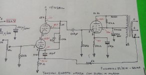
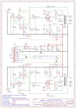
Hello guys, I bought this ampli a month ago, and asked the seller a schematic but he kindly sent a wrong one.....so I draw it following the circuitry of my amp, the first stage, the preampli, is a "cascode" configuration ( usually used on old tube TV tuners ).....and replaced the first filter capacitor that was 120uF !!!! ( maximum allowed for 5U4 is 32....) with a 47uF/450v.....attached the schematic of my amply.....I took also some voltages on several points on the ampli
please how can upload the schematic ?
please how can upload the schematic ?
YamaA700,
You are connecting the EL34 screen in Ultra Linear mode.
But then, you have an AC short to ground, the 33uF capacitor from the Ultra Linear tap to ground.
That will not work.
Either remove the 10k resistor and the 33uF cap. That will be Ultra Linear mode.
Or, keep the screen, 10k, 33uF cap connected together, but disconnect alll 3 of them from the Ultra Linear tap. Then disconnect the 10k from the Plate lead; and connect the top of the 10k to the B+ lead. That will be Pentode mode.
Last edited:
Hi 6A3,
yes the configuration is Ultra-Linear,
till now the amply has worked very well......with the 33uF capacitor connected.....
the only my doubt is the 10K resistor between pins 3 and 4 of the EL34......perhaps to suppress unwanted oscillations ?
also I have tried to replace the 5U4 with a more efficient tube, the GZ34/5AR4, the main anodic voltage raises to 310vcc....
Hi all, I bought this amp 2e hand some weeks ago. I found it lively but a bit harsh sounding. Then I tried gridstoppers on the EL34 - 1k- but this cutoff the high frequenties making the sound dull. In the mean time I replaced the EH 6SL7 by Sylvania and these gave a good inprovement. However the sound stayed dull. Then tried 334 ohm as gridstopper. Much better but still missing some highs. But the harshness is almost gone. Removed the stopper again. With the Sylvania it gives a good balanced sound.
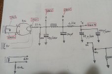
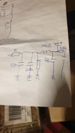
But the strange thing is that mine has a different schematic. I have made a drawing of it. Will make a foto and post it.
Now I will check the value of the c after the 5U4. I think in mine amp it's also 100 uF.
But the strange thing is that mine has a different schematic. I have made a drawing of it. Will make a foto and post it.
Now I will check the value of the c after the 5U4. I think in mine amp it's also 100 uF.
YamaA700,
I am not sure how I missed your message so long ago, but here is my delayed answer (sorry).
The 10k from EL34 pin 3 to pin 4 provides a purely resistive load across the 60% of the primary (the other 40% from B+ to the Ultra Linear Tap).
I am not sure of the schematic, but I think the 3.5k indicates the impedance of 100% of the primary.
At 60% of 3.5k, the 60% winding would be 3.5k x 0.6 x 0.6 = 1.26k Ohms (not 3.5k Ohms of the full primary).
So, the 10k/1.26k would only dissipate about 1/8th of the power. But it would make the load impedance that is presented to the EL34 not go real high at some frequencies where some loudspeakers have very high impedance.
. . . Example, a 2 way "8 Ohm" loudspeaker might have 35 Ohms at the bass resonance of 40Hz, and 25 Ohms at the woofer/tweeter crossover at 1500Hz.
Hello everyone,
I am getting into tubes, I am in the process of building a 300B based on a PCB (wich will be easy)
In the meanwhile, waiting for all my coponents to arrive, I baught a LAOCHEN EL34 amp for testing.
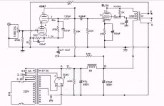
It is based on this diagram
The thing is that the sound is really too harsch. I tried tube rolling (tung sol EL34+6SN7GT, PSVANE 5U4G), changing 2 coupling caps with mundorf but I think the schematic is just not good.
Nos I have thransformers and valves on my hands. I thought about rewireing the whole thing but I can't find any schematic usung these 3 types of tubes.
Can anyone direct me in the right direction and provide me a good diagram?
the input transformer is 320V.

Just for the record. There's something wrong with the voltages indicated in the scematic in post #1.
The voltage drop over the 82K anode resistor is 225 - 120 = 105 V, so the current must be 105/82K = 1.28 mA. This fits with the indicated cathode voltage of 1.4 V, since 1.4/1K1 = 1.27 mA. However, the voltage drop over the 10K resistor in the B+ line is 340 - 225 = 115 V. The current through this 10K resistor would than be 115/10K = 11.5 mA. But the first stages of the two channels only draw 2 x 1.28 mA = 2.56 mA. So there's 8.94 mA 'missing'.
The cathode voltage of the EL34's is 15 V, which corresponds with a cathode current of 15 / 300 = 50 mA. The screen grid voltage is something like 340 - (15 + the voltage drop in part of the primary) = 320 V. But if you look on page 5 of the attached datasheet for the EL34, you will see that in order to get 50 mA of cathode current at a bias of - 15 V, the sreen grid voltage has to be even lower than 250 V (because the working point must lie a bit to the right of curve 1 in the datasheet).
Attachments
nickytheshaft,
The schematic has a center tapped Ultra Linear transformer. That would be 50% Ultra Linear (there are few 50% tap UL output transformers).
I hope they did not "simplify" (cheat) by using a center tapped push pull transformer. That would not have an air gap, and single ended amplifiers need an output transformer that has an air gap.
I did take a center tapped push pull output transformer; but I removed the interleaved E's and I's, and then re-stacked them, all the E's on one side, and all the I's on the other side, and put a layer of Kapton tape between the E's and I's. That formed a non magnetic 'air gap', so it could be used in a single ended transformer.
Can you see the air gap on those output transformers?
It looks like mine has a different setup. I have attached the schema I have drawn. It's still a rough sketch but good to give the idea.
I have changed the first C after the 5u4G rectifier to 47 uF and connected it after the 10 ohm resistor. It sounds a bit more relaxed now. Probably because there's less stress on the 5U4G. What do you think?
I have changed the first C after the 5u4G rectifier to 47 uF and connected it after the 10 ohm resistor. It sounds a bit more relaxed now. Probably because there's less stress on the 5U4G. What do you think?
Attachments
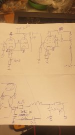
Hi Indaco, Thanks for your reply. I will study your schematic. I can see you added a switch for choosing triode versus UL. is UL not just pentode of tetrode operations. UL connections should be somewhere between the center and outer taps?
Did you make mods yourself?
Did you make mods yourself?
Hi dickdiy, the mods has been made in collaboration with french guys as you see in the schematics.
It was paid attention especially with the power supply and the decoupling caps (mkp in parallel), the B+ delay relay and the feedback network. The UL-triode switch is simple to set, just taken directly from the OT center-tapped pin via 1k c.c. resistor (in this case 33%) but also 43% is ok.
Also to swap from a pentode to a tetrode you can add a couple of spring wire connectors from pin 1 to 8 of the power tube.
I have two other alternate circuits before it, that differ only on the first stage, but finally this one was performed.
Did some more tweeking. I cut the tyraps around the wires and took them apart as far as possible. This ofcourse lessens the interfirence between the wires. I have to say this gave a major improvement to the sound. Next I will look at the various mods in this blog.
Yes, the 100uF cap was in a silly position paralleled with 47uF just after the rectifier tube. You have to see the max allowable capacitor for a L-C based upon your tube specs. Mine is 5931 and 47uF is at the limit (depending on the transformer resistance). You could check ti with PSUD.
Is there any bleeding resistor around?
Is there any bleeding resistor around?
Yes indeed. I was afraid the 5u4g would blow at a certain moment. There's a bleeding resistor yes.
The first thing I noticed was that there was no compensating cap in the FB loop making me wonder if the original configuration was getting into some oscillation. I suppose one could also try taking the FB from the primary side.
Indaco,
In your Post # 32 schematic, apparently you used a single ended output transformer with only B+, 2.5k, and 3.5k taps (And No UL tap).
Very Nice Idea!
No UL tap on a single ended output transformer? Then use one with multi-impedance plate taps, and wire the amp for 'UL' operation.
Root (2.5) / Root (3.5) = 0.845
With the plate connected to the 3.5k tap, and the screen connected to the 2.5k tap, that is 84.5% 'UL tap'.
- Home
- Amplifiers
- Tubes / Valves
- Need a good EL34-5U4G-6SL7GT schematic