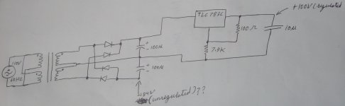
I am designing a power supply that supplies regulated +100V and -100V form a 110V 60 Hz AC source. I got the regulated +100V working but i am stuck with the -100V part. I cannot find a negative voltage regulator to regulate my output from the bridge rectifier. The voltage across my smoothing capacitor is unregulated -184V and i need to bring it down to -100V.
CAN ANYONE HELP ME PLEASE!!!!!
For reference I have attached my circuit
Thank You
CAN ANYONE HELP ME PLEASE!!!!!
For reference I have attached my circuit
Thank You
Attachments
I am designing a power supply that supplies regulated +100V and -100V form a 110V 60 Hz AC source. I got the regulated +100V working but i am stuck with the -100V part. I cannot find a negative voltage regulator to regulate my output from the bridge rectifier. The voltage across my smoothing capacitor is unregulated -184V and i need to bring it down to -100V.
CAN ANYONE HELP ME PLEASE!!!!!
For reference I have attached my circuit
Thank You
If you have another isolated transformer winding you can build another +100V regulator, connect the "+100V" terminal to gnd and use the "gnd" terminal as -100V. Works like a charm.
jan didden
Here is an example, easily configurable for -100V or any other voltage:
http://www.diyaudio.com/forums/powe...gh-voltage-regulator-circuit.html#post2417349
http://www.diyaudio.com/forums/powe...gh-voltage-regulator-circuit.html#post2417349
Bringing the voltage from 184v down to 100v with a regulator is going to produce a huge amount of heat.
Doing it twice would require a turbine to cool it with.
Can you change the transformer?
Doing it twice would require a turbine to cool it with.
Can you change the transformer?
I don't really want to change the transformer but if there is a better solution for my problem then certainly I would like to hear it.
I am designing a power supply that supplies regulated +100V and -100V form a 110V 60 Hz AC source. I got the regulated +100V working but i am stuck with the -100V part. I cannot find a negative voltage regulator to regulate my output from the bridge rectifier. The voltage across my smoothing capacitor is unregulated -184V and i need to bring it down to -100V.
CAN ANYONE HELP ME PLEASE!!!!!
For reference I have attached my circuit
Thank You
I would also need a 100v power supply but cant find a suitable voltage regulator for that. Which one have you used. Cant find any info for a "TLC783" ...
Losing 84v in any semiconductor is hard. Consider replacing the transformer so its closer to 100v for each DC polarity.
If the current required on the output isn't too high on the negative rail you could consider a design using a resistive divider or a basic resistor/ zener diode arrangement. For guidance you should use one of the many zener calculators.
If you cannot sacrifice a bit of current, you will need to use a pass transistor and use a resistor/ zener arrangement across its base to get the voltage to negative 110v DC , then reduce the last 10v using a LM337 regulator 1.25x R2/R1 +1 The 337 dislikes anything above 40v differential
But in this example you are asking it to process just 10v. The net result should be good regulation and ripple performance. Use protection diodes by referring to Nat Semi data, as any caps discharging could be traumatic.
You could consider the same for the positive rail, staging down with resistor /zener ( and pass transistor if current is a issue ) to 110v then a LM317 .
Hope this helps / Chris
I can't find anything on the TLC783C? What the hexx is it? I seriously doubt it can handle much current with 84 volts across it. How much outout current do you need?
If you could get by with only about 80V then a choke input filter might be worth
looking at. That would get your voltage before the regulator down to between 90
and 100v.
looking at. That would get your voltage before the regulator down to between 90
and 100v.
A Choke will regulate current, but not appreciably alter voltage. Define how much current is needed in the circuit then regulate down to 100v with a resistor and zener diodes using calculators widely available for zener regulation. Using a 337 after that will reduce ripple
and as already suggested with protection diodes should be ideal.
So view reduction in two stages simple resistor zener observing polarity for the zener with respective + and - supplies, then regulate the last 10v and reduce reduce ripple with a 337 for negative , and 317 on the + using 1.25x R2/R1 +1 see Nat Semi data for 337 and 317
Schematic to follow
Hope this helps / Chris
Last edited:
I don't know how this would work sonicaly
But lets say you use two small transformers back to back,
110V mains to 6V, and that connected to a 9V mains transformer, should give in the order of 103VDC rectified, Those were just the first two values of voltages I calculated, some may bring you even closer, I assume not much is needed in the line of current.
Oh, yes, I think there is an application note for AC regulation in the LM317 datasheet, this could maybe be applied between two transformers in a similar configuration as above?
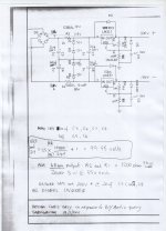
Attached Schematic reducing 184v dual rail to 100v Dual rail @40ma
all diodes 1N4004 caps on input 20uf @ 200v cap on adj 1uf @160v
resistors are 10 watt 1200 ohms then 5w -55v zeners
R1 on 317 and 337 are 240 ohms and 19000 ohms on R2 for 100v output
Observe all polaritys with dual rail
Hope this helps / Chris
all diodes 1N4004 caps on input 20uf @ 200v cap on adj 1uf @160v
resistors are 10 watt 1200 ohms then 5w -55v zeners
R1 on 317 and 337 are 240 ohms and 19000 ohms on R2 for 100v output
Observe all polaritys with dual rail
Hope this helps / Chris
Attachments
Attached Schematic reducing 184v dual rail to 100v Dual rail @40ma
all diodes 1N4004 caps on input 20uf @ 200v cap on adj 1uf @160v
resistors are 10 watt 1200 ohms then 5w -55v zeners
R1 on 317 and 337 are 240 ohms and 19000 ohms on R2 for 100v output
Observe all polaritys with dual rail
Hope this helps / Chris
I wounder if the design with that zeners to define the ground level is also good for higher output currents ( e.g. ~2 A) since you need the resistors R1 and R2 to limit the current for the zeners, isn't it?
I need also a +/- 100V power supply but with output currents up to 2 A. So I think it would be better to use two transformers or one transformer with secondary 2x115 V (primary 230 V) and regulate the voltage down to 100V like with the regulator in your circuit.
Would you agree?
There are a few ways, As you may appreciate 2 amps of current on each rail is a lot more than the 40ma of the schematic I posted reducing 184v x2 to 100v x2
When higher current is used there are usually specific load requirements - so I am asking is this an audio project or some other project you are designing ?
Unregulated
100v- and 100v+ at 2amps requires a transformer that is available - very few transformers offer 2x 71 VAC taps, but if you use 2 individual transformers with 35v 0 35v each and series the windings 70v ( with series windings you get half the current ), you will need 2 transformers rated at 300va each
The primary can be 120v if that is the voltage in your country - or 240v as the case may be. 35 0 35 is a very common winding so easy to get.
The first transformer use a full wave 35a bridge grounding the negative of the bridge rectifier and use 2200 uf of capacitance = 100v +
The second use a full wave 35a bridge ground the positive of the bridge rectifier and use 2200uf of capacitance = 100v negative
You can also apply some current regulation across each in the form of series inductance, in parallel with a 6 amp diode - so an easy answer and a good reliable PSU delivering 2 amps at 100v + and negative - . ( Whilst its tempting to use 10,000uf - 2200uf is ideal for 2 amps rule of thumb is 1000uf for every amp of current. )
Regulated
Requires higher initial voltage ie 40v 0 40v ie 80v on each transformer = 113v DC so we then design to lose 13v in regulation components
Pass Transistors like MJ15003, MJ15004 ensuring each are living at a safe input to output differential, here we can use a common
collector pass transistor and bring current to a zener stack by way of two resistors bypassing the middle with capacitance which if further capacitance is used on the base dramatically improves ripple
Or pass transistors and usual regulators LM317 and LM337 and applicable resistance 240 / 19000 ohms or 7815, 7915 with Zener stacks and protective diodes
Let me know about your project and if you need schematics ?
Cheers / Chris
Last edited:
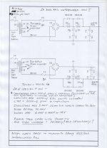
Unregulated 100v + and negative 2 amp supply with inductors and parallel diodes.
Note transformer shown is step up when this is step down ( it was the best I could find in Oregano software )
Please note this is a high voltage schematic, and observe all precautions with high voltage ! and dual polarity !.
Capacitors are 4x total series connected 63v 2200uf ( 2 in each leg) providing 2200uf total in each rail, Inductors are the the common 16- 18mm toroids rated at 5 amps
Transformer is 2 x secondary 35v windings series connected to provide 70vac which is
99v DC. The schematic provides two transformers 1 is for the positive rail the other is
for the negative rail each delivering 70v to a 35 amp 400v bridge suitably mounted . Diodes are 6 amp 400v or higher
Fuses are shown on primary and secondary AC windings, if DC protection is also required
use 4x parallel 1ohm 2 watt resistors in each rail prior to first inductor or other protection for desired limiting.
Cheers / Chris
Attachments
Dear Chris,
thank you very much for your reply!
I was bussy yesterday and wasn't able to response.
The 2A power supply unit would be for a high dynamic piezo driver amp, where I use the LME49830 (audio) op amp (+/- 100V supply, 50mA out). Of course 2A output of the power supply unit would be more than enough but I plan to drive more of those pieozo driver in parallel and I'm afraid a regulated power supply is needed.
Thank you also very much for your schematics. I've learned a lot from it.
I will apply your tips for a regulated power supply and will post a schematics here for discussion.
Cheers,
Olli
A switching regulator would be the way to go. Use two switching regulators, one for +100V and the other for -100v. You need your transformer to put out two separate isolated windings or two transformers with a single output. The issue is finding a buck regulator that can output in the +100V. I did a search for PFC controllers since they can operate at high voltages and I found this TI part:
UCC29910A Buck PFC Controller
http://focus.ti.com/lit/ds/slusak8/slusak8.pdf
This controller operates at 100 khz, which should make noise filtering easy with a standard PI Filter.
Another way is to build a Buck regulator using PWM controller that supports feedback perhaps the TL598. but you need to use a mosfet gate driver to drive the mosfet. This would be a sort of roll your own regulator. Using a high switching frequency would permit you to filter out the switching noise using small components in a Pi Filter. You need to use a R-R voltage divider to drop the voltage for the PWM controller, but since the PWM controller will use very low power this shouldn't be an problem. Just use a TVS diode in parallel with the lower Resistor to prevent voltage spikes from causing an overvoltage in the PWM controller.
Hi okmog
With 113v DC in on each rail ie 80v AC. The calculation for 100v + and - out and using the earlier schematic with 317 and 337 at 50ma for your piezo project is 134 ohms @ 2 watt for the zener resistors, but use 5 watt as heat alters resistance and use 3x 33v zeners for each rail and make these 5 watts each raising them off the board as close to 10 watts is consumed in the zeners.
Re switchmode there are many advantages, but also many complexities.
Cheers / Chris
Hi Chris,
regarding your schematics of a +-100 VDC unregulated power supply posted above.
Wat are the diodes parallel to the chokes good for? -- since the current is going thru the diodes instead thru the chokes, the would bypass the chokes, wouldn't they?
Cheers,
okmog
regarding your schematics of a +-100 VDC unregulated power supply posted above.
Wat are the diodes parallel to the chokes good for? -- since the current is going thru the diodes instead thru the chokes, the would bypass the chokes, wouldn't they?
Cheers,
okmog
Last edited:
- Status
- Not open for further replies.
- Home
- Amplifiers
- Power Supplies
- Need a -100V Voltage regulator