Whenyou say 'I connect the NE5534's', do you mean you connect also the whole +/-12V generation circuitry?
Jan
Jan
The +/- 12v is always connected, the +12v feeds the 5v LDO for PCM1794 (I don't use VBUS directly).
So those figures show a significant power increase when the NE5534's are plugged in. I suspect, and I'm still analysing, the boost chip can't keep up and becomes inefficient (I've seen this run away condition before with boost). Thing is, the chip is 2A rated minimal and 3A nominal so it should have no problem, and the PCB design is tight with no flaws common to buck/boost design topology.
So those figures show a significant power increase when the NE5534's are plugged in. I suspect, and I'm still analysing, the boost chip can't keep up and becomes inefficient (I've seen this run away condition before with boost). Thing is, the chip is 2A rated minimal and 3A nominal so it should have no problem, and the PCB design is tight with no flaws common to buck/boost design topology.
More analysis:
1.
Disabling the -12v generation takes consumption down about 0.2A at VBUS. That leaves about 0.8A for +12v (which is also powering the 5v and which I know from before installing NE5534's takes about 0.15A). Therefore 0.65A is being used at VBUS for NE5534's
(this is not the consumption used at the NE5534 side, remember I'm measuring the input only before boost).
2. Heat measurements show the boost becoming the same sort of temp as the NE5534's. I don't think it's the problem now.
3. Replaced the boost with a MT3608 which is a cheap equivalent. Exactly same amperage measured. I'm now fairly sure that for some reason the NE5534's are burning more power than advertised in TI datasheet (sleu037.pdf) with no variance on component values. As stated all components are smd and tight with double via's where necessary.
Currently stumped.
You really should try to measure that additional load. Or, next best, attach a load that mimics the NE5534's: 12 x 4mA = 50mA @ 24V = ~500R.
That will tell you right away whether it is the NE5534's or something on the converter.
BTW a converter with a 2A switch cannot deliver 2A. Check the max duty cycle with the L you use.
Jan
That will tell you right away whether it is the NE5534's or something on the converter.
BTW a converter with a 2A switch cannot deliver 2A. Check the max duty cycle with the L you use.
Jan
I'm unable to insert to measure unfortunately.
Aware that it can't deliver 2A but still well within limits.
I've made some further testing, I've PP-v of 118mV on the -12v and 110mV on the 12v which isn't great. The 3v and 5v are ~30mV. The 1.2MHz of the boost is making it through everything according to the scope but that can be expected.
On the NE5534 side, x8 are receiving 0v on pin 2&3 (PCM1794 x2 in mute) and presenting -4.64v on the outputs, or half the expected 9v, to the remaining x4. I believe this is correct. In the schematic posted earlier can see this would draw 6.4mA through 2x360R resistors, 8 times so 52mA loss on top of the 12 x 8mA max. In other words, still I can't explain where the loss is. 🙄
OK I've removed half the NE5534's and have noted a 0.45A decrease. So...
Assuming the boost is working well (I don't notice that much heat) and say a 85% efficiency. 5*0.45*0.85 = 1.9125W
Voltage +/- delta is 25v.
12 * 25v * 4mA = 1.2W
And 8 of the chips are loosing 6mA through the output.
8 * 25v * 6mA = 1.2W
= 2.4W and I'm expecting 1.9125W
Which means they're working correctly, right?
Corrected >>
OK I've removed half the NE5534's and have noted a 0.45A decrease. So...
Assuming the boost is working well (I don't notice that much heat) and say a 85% efficiency. 5*0.9*0.85 = 3.8W
Voltage +/- delta is 25v.
12 * 25v * 4mA = 1.2W
And 8 of the chips are loosing 6mA through the output.
8 * 25v * 6mA = 1.2W
= 2.4W and I'm seeing 3.8W, which means either the chips are taking a bit more than 4mA each or the boost isn't 85% efficient.
If the chips take 8mA that's 2.4W + 1.2W = 3.6W almost bank on the money.
Which means they're working correctly, right?
And 8 of the chips are loosing 6mA through the output.
?? What is the load on those outputs then? Is there a DC output??
Jan
When the PCM1794 is in mute I see -4.5v output from the 8 5543's. You can see from the earlier schematic I posted that this can go through two resistors to ground, 360 x 2.
The final 4 5543's get the same -4.5v so have 0v output.
The final 4 5543's get the same -4.5v so have 0v output.
So its not the 5534's that draw all those current, it's the load resistors.
Why is there a 4.5V DC offset on those outputs? Is there a DC output on the DAC output?
You can measure the voltage across those 360R resistors to calculate the current they draw.
Jan
Why is there a 4.5V DC offset on those outputs? Is there a DC output on the DAC output?
You can measure the voltage across those 360R resistors to calculate the current they draw.
Jan
Yes, the PCM1794's is driving both at full outputs (but same polarity) which for the last 4 op-amps gives 0V output. It means the first 8 op-amps are at max output swing (-4.5v).
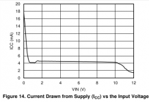
I think I posted this in another thread already but I can save a lot of power by switching to +/- 7.5v. 4.5v/720R = 6.25mA, I think based on a graph in the datasheett 5534 will be comfortable sinking this running at +/- 7.5v.
Graph shows current output for a 11v signal using 12v power rails. 5534 needs 2V headroom at least, I'm drawing a bit more current hence thinking at least 3V headroom. Even 4.5V headroom (double) is a good power saving.
Attachments
Not at all but I don't see anything wrong with them other than higher consumption. To slot in any replacement has to be able to output at least 7mA (max at 4.5v).
Practically any opamp these days can output 10's of mA, that should be no problem. If push comes to shove you could select one with a standing current of 1 or 2mA instead of 4, which for 12 opamps would save you 20 or 30mA. Not sure it would be worth it in the grand scheme of things though.
Jan
Jan
- Home
- Amplifiers
- Chip Amps
- NE5534, Vcc > +/-10v pointless for 9v balanced output?