Hopefully the title says it all. In the BurrBrown (Ti) document attached the NE5534's are provided with 15v. Another design I've seen uses 12v, while the peak output for balanced is 9v.
The NE5534 isn't rail to rail and requires 1v headroom as a minimum. Therefore, in this application is there any point in going above 10v? As I see it it'll just waste the excess as heat in the op-amp.
The NE5534 isn't rail to rail and requires 1v headroom as a minimum. Therefore, in this application is there any point in going above 10v? As I see it it'll just waste the excess as heat in the op-amp.
Attachments
Just keep in mind that most music has ~ 14 db peak-to-rms content. That's the minimum amount of headroom needed; most pro systems try for 20 db. For a +4dbm output (1.23 volts) that needs 12.3 volts, and the dropout voltage for an NE5534 is probably closer to 2 volts into a 600Ω load---thus the need for 15 volt supplies.
The excess heat would be minimal, not really a factor for the opamp.
The advantage of higher than absolute minimum supply voltage, is that you get those 9V with very little distortion. Trying to get 9V out of a 10 or even 11V supply might work, but you are on your way toward clipping, and distortion significantly rises towards that point, even is you are not actually clipping yet.
As a matter of routine, you try to use as high as possible supply voltage in these circuits for maximum output with minimal distortion.
Jan
Last edited:
Why would you even want 9V RMS in a controlled environment?
Yes, I have worked where +24dBm (12.2V) was considered minimum but we never intentionally worked that hard, it was to cover mistakes without gross clipping.
> ~ 14 db peak-to-rms content.
This is coming off a DAC. The rated voltage is for "all digits", it can't get any higher.
Yes, I have worked where +24dBm (12.2V) was considered minimum but we never intentionally worked that hard, it was to cover mistakes without gross clipping.
> ~ 14 db peak-to-rms content.
This is coming off a DAC. The rated voltage is for "all digits", it can't get any higher.
Nope, the chip requires 3V headroom - check the datasheet for output swing.The NE5534 isn't rail to rail and requires 1v headroom as a minimum. Therefore, in this application is there any point in going above 10v? As I see it it'll just waste the excess as heat in the op-amp.
Normally in a prof. audio environment you'd run at +/-19V and expect to see 11Vrms max from such opamps. If you want 9V peak (6.4Vrms), +/-12V is the minimum supply voltage needed.
For a rail-to-rail opamp you'd normally expect around some definite dropout on the outputs if under a few k load - no output section can drive to the rails under load.
If power consumption is an issue there are lower powered opamps than the 5534
Hopefully the title says it all. In the BurrBrown (Ti) document attached the NE5534's are provided with 15v. Another design I've seen uses 12v, while the peak output for balanced is 9v.
The voltages are 2x4,5Vrms meaning +/- 6.364V peak, possible with 10V rails.
But the I/V stages see very short current glitches which might drive the amp into saturation, better to have more headroom with the recommended +/-15V rails.
The filter stage takes out these glitches and also reconstructs the original waveform.
The 9V balanced in mono mode are just the same 4.5V but with opposite polarity.
bansuri -> 9V balanced XLR is peak not RMS, and +/- 9v
Mark ->
My active speakers have 10k impedance, typical for XLR. Looking at the TI datasheet (pg 7) again I see there is a +/-2v dropout at +/- 15v Vdd up to 100Khz.
So adding a little extra, something around 11.5V should cover 9V peak without any distortion into a 10K load.
Let me know if that's wrong!
I should also add, 8 x NE5534's with +/- 12v, after the boost and inverter stage, burn about 600mA /6V at idle. I was hoping to get it down to 0.5A.
The current does not depend on the voltage, or only very weakly.
See also post # 3
And max supply current for NE5534 is 8mA, 8 x = 64mA if they are all at max, which they will not be, but not 600mA by a long shot
Jan
See also post # 3
And max supply current for NE5534 is 8mA, 8 x = 64mA if they are all at max, which they will not be, but not 600mA by a long shot
Jan
Last edited:
bansuri -> 9V balanced XLR is peak not RMS, and +/- 9v
Mark ->
My active speakers have 10k impedance, typical for XLR. Looking at the TI datasheet (pg 7) again I see there is a +/-2v dropout at +/- 15v Vdd up to 100Khz.
So adding a little extra, something around 11.5V should cover 9V peak without any distortion into a 10K load.
Let me know if that's wrong!
look at the schematic from data sheet

Some real life measurements.
I have 12x NE5534's consuming +/- 12v.
The input is 5v/0.98A. 0.06A is used by other chips, so 5V/0.92A
Which goes through a TI buck at ~85% efficiency = 3.91W dissipation
= 0.325833333333W each
/ 24 = 0.01357638A each
Considerably over 8mA.
I have 12x NE5534's consuming +/- 12v.
The input is 5v/0.98A. 0.06A is used by other chips, so 5V/0.92A
Which goes through a TI buck at ~85% efficiency = 3.91W dissipation
= 0.325833333333W each
/ 24 = 0.01357638A each
Considerably over 8mA.
Why do yoiu not measure the current in the 12Vrail directly?
The 85% refer to high current so if the PS is rated for 500mA and only 60mA are used, the efficiency has gone down to 40% maybe.
The 85% refer to high current so if the PS is rated for 500mA and only 60mA are used, the efficiency has gone down to 40% maybe.
There can also be some issue with oscillations. watch the idle current and touch the opamp case with your thumb, when there is a change that indicates oscillation
Some real life measurements.
I have 12x NE5534's consuming +/- 12v.
The input is 5v/0.98A. 0.06A is used by other chips, so 5V/0.92A
Which goes through a TI buck at ~85% efficiency = 3.91W dissipation
= 0.325833333333W each
/ 24 = 0.01357638A each
Considerably over 8mA.
I don't know your circuit, but 8mA is max supply for a 5534.
Nominal it is 4mA, so with 12 random units I would expect to get very close to 48mA total. Check the data sheet.
Show us the circuit, and we will show you where the bulk of the current goes; it is not into the 5534's.
Your buck converter might be a lot less efficient at this low load, you should really measure.
And, again, those 4mA (or 8mA max) of the 5534 do not go down when you go from +/-12V to +/-10V. You're on the wrong track.
Jan
Last edited:
No I'm measuring at the boost input which is 5v @ 0.89A. This is with the alternative TI chip I found LMR62421. It boosts to +/- 12v. Without any NE5534 chips installed it pulls 0.06A for the PCM1794 etc, so 5v @ 0.83A is left. Assuming the boost is 85% efficient that gives 5v @ 0.7A or 3.5W or 24v @ 0.145833A. Now divide that by 12 and each NE5534 is burning 0.0121528A.
You can't do that assuming 85% efficiency! That's just pie in the sky. With such a low load, that efficiency goes down the drain.
What you DO know is that with 12 NE5534's they will burn close to 48mA nominal, then work backwards and work out the efficiency. That's a logical way.
Jan
What you DO know is that with 12 NE5534's they will burn close to 48mA nominal, then work backwards and work out the efficiency. That's a logical way.
Jan
Last edited:
I'm back. After a revised circuit design I'm at an even worse position.
Quick summary, I have VBUS which goes through a 3.3v LDO and a boost which creates +/- 12v, I then have a 5V LDO and the +/- 12v go to the 5534's.
I measure current at VBUS. The boost is a lmr62421, it's the only one I could find in stock (TLV61048 would be preferred), and has a min current switch of 2A.
With no 5534's installed I see 0.17A at VBUS. Giving the lmr62421 is around 80% efficient and the LDO drops the 12v to 5v as heat I would say something like 5v/0.1A is being consumed. This perfectly matches the load; 2x PCM1794's and a DIR9001 spdif converter.
I now connect the 12x 5534's and load jumps to 0.96A. Two conclusions:
1. the lmr62421 can't keep up with the load. It does appear to be the case when I measure 12v, as it should be about 13v and it's at 11.5v.
2. the 5534's are dropping too much.
As you can see from the pcb layout everything is tight, plenty of capacitance on input/output. Based on what everyone has been saying the 5534's shouldn't be adding that much load. I'm puzzled.
Attachments
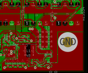

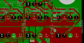
Forgot to add, the NE5534's are using TI's reference design to the letter, with smd components, very tight.
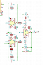
Part schematic of the NE5534 side which follows the reference design to the letter. You can see that due to smd's it's nice and tight. I could be wrong but I don't think the problem is here. I suspect there's something not right on the -12v line generation.
Boost resistor values are incorrect on the schematic but are correct on prototype to generate 12.5v. Measuring 11.3v at the moment.
Boost resistor values are incorrect on the schematic but are correct on prototype to generate 12.5v. Measuring 11.3v at the moment.
Attachments
- Home
- Amplifiers
- Chip Amps
- NE5534, Vcc > +/-10v pointless for 9v balanced output?