I build this opamp kit from ebay... NE5532 Volume Control Board KIT 10 Times PRE AMP DIY KIT | eBay
to go with the chipamp kit(very similar to this: High Performance Audio 60WX2 LM3886TF Power Panel Power Amplifier Board DIY KIT | eBay - my boards are blue though and slightly different components) I got. For some reason i'm getting a ton of noise from the preamp/volume control board. It's pretty much useless. When I turned the volume all the way up the hum seemed to go away (that sorta defeats the purpose of why I got the board - and it still didn't eliminate the noise 100%) I have tried grounding the knobs which didn't do anything. I tried another pot I had which didn't do anything. I'm kinda lost at what to do here.
I was running it off the transformer for the chip amp (while running the chipamp - i used the 12v secondary pair), so I tried another one, that made no difference.
Did I buy crap? (probably) but there has to be something I screwed up.
With buying crap in mind, can someone recommend me a preamp that might go nicely with with the chip amp? Looking for a kit or something from ebay ideally.
Though this is a simple kit, you probably realize that it's impossible for us, other than to guess at likely newb errors, how you may have have assembled the kit (if that was necessessary).
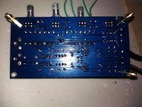
Obviously, we need clear pics of both sides of the board to check the orientation of caps , ICs and the solder joints and possibly wiring errors. Other than that, there will be few issues apart from unlikely parts faults or possible incorrectly fitted parts. (5532s are already very low cost ICs direct from OEMs and even low grade caps will not cause noise at the extreme level you quote.
First, carefully recheck the orientation of caps, that the voltage regulators are in the right positions and as a BIG priority, verify that DC voltages match nearly to those on the schematic diagram. Are you confident that resistor values are correct according to colour coding?
Note that without a Multimeter of some description, you cannot be sure anything will have a chance of working properly. BTW, is the chip amplifier known to work properly without the preamp?
Well the chip amp does work fine with out a preamp, so maybe it's not needed, but I thought a preamp was a good idea in general before going into a poweramp.
I'll take some pictures. I'm almost 99% positive all the stuff is wired correctly (not my first electronics project, but my first audio one). The circuit diagram they gave me was pretty ghetto so that wasn't much help.
I'll take some pictures. I'm almost 99% positive all the stuff is wired correctly (not my first electronics project, but my first audio one). The circuit diagram they gave me was pretty ghetto so that wasn't much help.
Most music systems need a volume control.
Most Chipamps do not need a conditioning stage in front of the input.
Combining those, I arrive at
Some gain may be required to drive the chipamp to just reach clipping with your smallest source voltage.
The gain stage or buffer should be beside the volume control and NOT at the chipamp.
Most Chipamps do not need a conditioning stage in front of the input.
Combining those, I arrive at
Some gain may be required to drive the chipamp to just reach clipping with your smallest source voltage.
The gain stage or buffer should be beside the volume control and NOT at the chipamp.
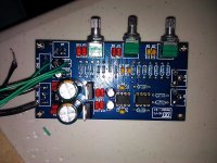
So what do we see there? 2 DIP8's (probably dual OpAmps like 5532), some R/C beneath some pots (assuming baxandall) and a 7812/7912 power supply? I don't even find the usual small caps at the NE5532 power pins... Perhaps it's not crap in terms of the sum of material you're getting for your money, but it's not "hi-fi" (as the pcb print shows) - but hey, the guys in china made a 2-sided PCB for it 🙂
Okay, will stop kidding now. Pictures will be rather useless, better provide us with the schematics as long as you have it. And for the first try better go with a simple buffer and a volume pot driving your chip amp, that can be easily built even without a sophisticated PCB (reusing some parts of your "preamp").
BR,
Holgi
Lets focus on the reasons this kit doesn't work properly and so make a reply to the OPs first request before dismissing it for alternatives. Unless we have a clear indication, such as a pic, showing the build is according to the design or not, we aren't in a position to help, are we?
I know that this kit works well enough, as a friend has built what seems an identical one in the last year. This was noisy initially and, like any preamp with plenty of gain, it needed shielding in a metal case for lowest noise. I'm not saying this is the problem but it could be a part of it.
I know that this kit works well enough, as a friend has built what seems an identical one in the last year. This was noisy initially and, like any preamp with plenty of gain, it needed shielding in a metal case for lowest noise. I'm not saying this is the problem but it could be a part of it.
Last edited:
Lets focus on the reasons this kit doesn't work properly and so make a reply to the OPs first request before dismissing it for alternatives. Unless we have a clear indication, such as a pic, showing the build is according to the design or not, we aren't in a position to help, are we?
Don't get me wrong. I totally agree, but without even having seen the schematics it is just guessing around. Maybe it was a bit too ironic, sorry for that 😎
BR,
Holgi
First thing that pops up into my mind is ground loops (hum..).. Because to make an NE5532 oscillate, things have to be -really- bad..
15 VAC is the supply voltage. Do you have that? Do you have any documentation? Have you contacted the supplier?
Power the preamp with a small separate power supply and your problem will be solved.
I have done that.
Sorry for the delay on the pictures.
Please note that I had unsoldered the volume pot while I was debugging. There are also a couple probes connected to the caps that I used while debugging.
The board was connected cleanly when I first noticed the problem.
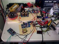
I first used another transformer I had (not the one shown with the tube buffer thingy, it's to the right of the picture of my work bench) and still had the problem. I then desoldered the pot and tried another one (hence the probes) I then started looking at the caps which I had assumed were the ones for smoothing the power.
Please note that I had unsoldered the volume pot while I was debugging. There are also a couple probes connected to the caps that I used while debugging.
The board was connected cleanly when I first noticed the problem.
I first used another transformer I had (not the one shown with the tube buffer thingy, it's to the right of the picture of my work bench) and still had the problem. I then desoldered the pot and tried another one (hence the probes) I then started looking at the caps which I had assumed were the ones for smoothing the power.
Attachments
Last edited:
Hi,i have same problem,the only way to reduce it is to remove thos 100pf capacitors and then you still have hum but at lower level.
i used LPF for power supply also and still nothing - i think its just bad design
i used LPF for power supply also and still nothing - i think its just bad design
Er...what 100 pF capacitors? One problem with this kit design can be that there are not enough caps - i.e. coupling caps, to eliminate DC at the input in some applications. That was a problem I had to begin with........remove thos 100pf capacitors and then you still have hum but at lower level.....
Here, I can only see 2,200uF and 100uF electrolytics with some small, bypass MKT caps of 0.1 and 0.22 uf in the power supply. There are also 10uF output coupling caps. This makes it a fairly standard design. The other caps are necessary for the tone filters. confused:
Quite some time has passed now. Sereal, (if you are still reading) did you find a solution?
a simple ac feed probably won't work. You need two windings or a winding with a center tap to supply the preamp. Your pictures don't show that.
Hi There,
Without schematics or o'scope readings of the various signals, it's tough to say. But, from the appearance and source (most likely the kit originated in China), I have some suggestions to try:
1) Change the op-amps - SO MANY components from China are remarked (like an LM1458 marked as an NE5532), used, rebranded (different OEM), or fall-out (doesn't meet OEM specs) parts.
2) Add 5 to 100pF caps across the output and -input pins. This will eliminate the possibility of parasitic oscillations. I know, the audio purists loathe caps, but they are standard on virtually all OEM audio electronics and only come into play > 250KHz.
3) Add a Zobel filter on the output of the preamp. It's just a simple R/C low-pass filter that adds a slight load > 100KHz. Something like 22ohms + 20nF may work, but try some values and see if it makes a difference.
4) Make sure Iib (input bias-current - slightly higher for the NE5532's bi-polar input transistors vs. FET inputs). All this means is something like a 100K resistor from the +input to ground. Some preamps leave the +input floating with just a coupling cap connected.
5) Change circuit topology - you would need to reverse-engineer the schematics and see how it is configured. Some preamps use the pot in the feedback-loop to vary gain, while most use the pot as an input-voltage-divider with the op-amp's gain fixed. The latter is usually preferred.
Again, these are just some off-the-cuff suggestions. These are all issues I've encountered in the professional-audio industry, but without more specifics about your circuit and issues, it's tough to say. But, everything I suggested is relatively cheap and quick to try.
Please let us know what fixes it!
Paul
Wow, I just looked at the trace routing from the output of the op-amp to the output caps and I think I see the problem:
It looks like the output of the op-amp runs through the pot to ground (the pot acting as a voltage divider) and the pot's wipers connect to the output caps and thus to the outputs.
If so, this is a stupid design. It works, but the preamp's Z-out swings from very low (at min and max volume) to 1/2 the pot's value at mid-level. This would explain why you have low noise at min and max volume, but noise in between. In the high-Z range in the middle, the input of your power amp is susceptible to radiated noise, hum, etc.
So, I would recommend my fifth suggestion above. Carefully trace the inputs, outputs, pot connections, etc., and have the input signal pass through coupling caps and through the pot to ground. The pot's wipers then feed the signal to the + input of the op-amp. Then you can route the op-amp's outputs directly to the output connectors (and instead of output coupling caps, just add low-value series resistors). This should all but eliminate your noise problems. Of course this assumes the rest of the circuit is inherently quiet and stable. If there is still noise, go through suggestions 1 to 4 as well.
Hi Sereal!Sorry for the delay on the pictures.
Please note that I had unsoldered the volume pot while I was debugging. There are also a couple probes connected to the caps that I used while debugging.
The board was connected cleanly when I first noticed the problem.
I first used another transformer I had (not the one shown with the tube buffer thingy, it's to the right of the picture of my work bench) and still had the problem. I then desoldered the pot and tried another one (hence the probes) I then started looking at the caps which I had assumed were the ones for smoothing the power.
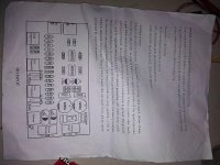
Give me the circuit of the preamplifier with tone control.
thank you
I can't see a schematic.
Is this a volume control similar to this? Hi-Fi Headphone Amplifier I've breadboarded a similar circuit sans output buffer (never employed it) and it worked without a hitch the first time.
Is this a volume control similar to this? Hi-Fi Headphone Amplifier I've breadboarded a similar circuit sans output buffer (never employed it) and it worked without a hitch the first time.
- Status
- Not open for further replies.
- Home
- Amplifiers
- Solid State
- NE5532 Issues