So as the circuit stands and with a genuine 5532 I would expect to see at least around -0.5 volt offset at the opamp output.
Checking the offset with nothing connected would go a long way to confirming (or otherwise).
Thanks for the pointers...measured dc at 100mv /ch for NE5532
@Butcher
+- supply rails is NOT battery. Unless you use two of them.
2x banks of 10 Nimh
Place a suitable capacitor in series with R3. 22uF etc.
That will stop the DC offset, if any.
Do you mean r5 ?
If r3 what side ? between it and gnd or after r3 ?
I was going to say that 100mv sounds reasonable but it actually sounds to low tbh 🙂
Unless you did other tests I guess we will never know although you could try measuring the supply current (either rail) and see if the current is correct for a 5532.
Adding a cap in series with the output (R5) would be the surefire way to kill any offset issue. Be sure to add something like 100k to ground after the cap to provide a DC path and so ensure the cap isn't 'floating'.
Adding a cap in series with R3 reduces the DC gain of the amplifier to unity (1) at DC but will not necessarily reduce the final offset to zero.
A good circuit design would actually do both and have both caps fitted.
@Mooly
Of what value do you speak, ? master 🙂
Adding a cap in series with the output (R5) would be the surefire way to kill any offset issue.
Of what value do you speak, ? master 🙂
post20 sch for the PSU.
Don't install C3, 4, 5, 7
Instead read about snubber and install an R+C snubber across each secondary, if you experience ringing on the supply rails.
Don't install C3, 4, 5, 7
Instead read about snubber and install an R+C snubber across each secondary, if you experience ringing on the supply rails.
+- supply rails is NOT battery.
I think Bob was explaining how to generate a + and - supply from a single battery, by creating a mid-point and call that 'ground'.
Jan
@Mooly
Of what value do you speak, ? master 🙂
The cap value used when combined with the impedance of the following stage will set the low frequency roll off point. If we say that a 100k pull down resistor is used and that worst case you might be driving a 10k load... which is pretty low... then a 4.7uf would give a cutoff point below 5Hz.
So the cap need not be massive.
"2x banks of 10 Nimh"
Got you. don't short the batteries out!!!
Making design from vero board is what I'd do.
Using JFET i/p op amp (dual or quad) would be better, although the NE5532 is an ok opamp for audio, by all accounts. Is meant to be "low noise". If using a quad-opamp, don't forget to ground the unused i/p's ! The unused o/p's can be left floating (not attached to anything).
Having imbalanced power supply rails can cause DC offsets at o/p too.
Damn, I 'd start by building a p/s first. Using LM7815 and LM7915's. Just my 5c.P reamp board should have a ground plane ideally as well for low noise.
Owning a +- lab supply with current limiting would be ideal for prototyping! Current limiting p/rail could be limited to say, 100mA (or less) to prevent any mishaps!
Or even using a clean REGULATED and FILTERED 19V laptop single rail p/supply would be ideal (and safe). Then build single rail preamp design... Up to you really! I am sure you will get it up and running! A good fun (and practical) project...
Last edited:
Imbalance in the rails has no effect on offset. Even if you had +5 and -30 or +30 and -5 volt rails, the offset would be unchanged. The only effect would be asymmetrical clipping.
A fet opamp like a TL072 has considerably lower power consumption than a 5532 which could be important for battery use.
A fet opamp like a TL072 has considerably lower power consumption than a 5532 which could be important for battery use.
"Imbalance in the rails has no effect on offset. Even if you had +5 and -30 or +30 and -5 volt rails, the offset would be unchanged. The only effect would be asymmetrical clipping."
Oh yes, true (my bad, thanks Mooly for correcting me). With lower voltage on one side of rail, clipping is possible on that side of the o/p waveform above a certain i/p level.
1.4-2.5mA for the TL072 vs 6-16mA for the NE5532. Big difference! Be careful with the TL072 as i/p pins can be sensitive to static discharge into the gates. An 8 pin socket is a good way of playing with opamps.
Oh and bypass those two 47uF electros on the supply rails with a film or ceramic cap, say 0.1uF (100nF). Fit beneath the board on the cap legs.
Last edited:
Many thanks all for your advice.
Thought I should post where I have got to using your recommendations.....
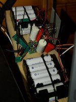
Some of this is just what was in the parts box to hand.....
so as Mooly surmised the first NE5532 was perhaps a fake....but luckily I inserted it in haste( and 180 degrees out ) one too many times and watched it's demise in spectacular fashion. 😀
The next NE5532 measured ~300-400 mv dc so perhaps was the real deal.
Changed R4 several times and settled on 56k.
I added ~8uF coupling cap to the output and 100k to ground. Things started to happen...good things..
Added 1uF in series to the inputs as advised by Bob.
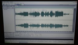
Tried upping R5 but it caused the M-Audio firewire box to throw a fit and freeze the adobe app on my pc. Left it at 68R.
Tried some other op-amps.... OPA2604 and LME49880 DIP Version Dual JFET from diyinhk.
Still testing but the OPA2604 seems to be more suitable in this circuit.
Both are better than the NE5532.
DC is unmeasureable on the output so all good there.
Will test with some recordings over the next week and report.
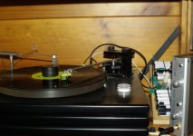
Some pix attached...I'm sure you will all shudder at my layout and point to point soldering but it has been quick to trial and once it is all working I will consolidate and build a power supply.
Again, thank you all for your input, it has been so helpful !.
Thought I should post where I have got to using your recommendations.....
Some of this is just what was in the parts box to hand.....
so as Mooly surmised the first NE5532 was perhaps a fake....but luckily I inserted it in haste( and 180 degrees out ) one too many times and watched it's demise in spectacular fashion. 😀
The next NE5532 measured ~300-400 mv dc so perhaps was the real deal.
Changed R4 several times and settled on 56k.
I added ~8uF coupling cap to the output and 100k to ground. Things started to happen...good things..
Added 1uF in series to the inputs as advised by Bob.
Tried upping R5 but it caused the M-Audio firewire box to throw a fit and freeze the adobe app on my pc. Left it at 68R.
Tried some other op-amps.... OPA2604 and LME49880 DIP Version Dual JFET from diyinhk.
Still testing but the OPA2604 seems to be more suitable in this circuit.
Both are better than the NE5532.
DC is unmeasureable on the output so all good there.
Will test with some recordings over the next week and report.
Some pix attached...I'm sure you will all shudder at my layout and point to point soldering but it has been quick to trial and once it is all working I will consolidate and build a power supply.
Again, thank you all for your input, it has been so helpful !.
Attachments
Last edited:
Sounds like you are getting there. The OPA2604 is (was 🙁) a favourite of mine but production problems mean it is no longer available from recognised outlets... so if you see any for sale that look to good to be true then beware.
Yes, 300 to 400mv sounds in the right ballpark for a genuine 5532 in your configuration.
The value of R5 once it is above a few tens of ohms should have no effect on the 5532 at all. Its only job is to isolate the opamp output from possible capacitive effects that could cause instability and just a few ohms does that. So whatever happened seems unrelated to the basic circuit. Going higher in value simply attenuates the output as the value of resistor then interacts with the input impedance of the following stage. Even a 10k for R5 would work OK with most typical line inputs.
So dunno on that 🙂
Also, with no DC offset at the o/p, there is no need for a coupling capacitor.
Tip for IC insertion orientation. Get a twink pen and mark where the side of pin 1 is on the PCB and IC. Even when tired, One will never insert incorrectly.
Fake IC's ? I have heard of fake power transistors! But never fake IC's. what is the World coming to?
At tech, I smoked an op-amp. I think another student had done something stupid and returned IC to box where they resided. I switched on p/s and the top of the IC flew off after mini-nuke and hot the roof. The tutor came over and asked WTF? I demonstrated that I had wired correctly but I failed to set current limit on the p/s!
- Status
- Not open for further replies.
- Home
- Source & Line
- Analog Line Level
- NE5532 circuit.What to change to increase amplification