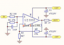
NE5532 preamp/buffer.. (Schematic attached) Running from battery@~14.5 volts+/-
What resistors do I need to change to increase the amplification ? Seller claims 3x as shown and this is too low.
Use case= I am wanting to amplify the output of my Moving Magnet Phono cartridge and record it. (yes I know it will not be RIAA equalised...that is what I want 🙂..)
I am feeding an M-Audio Firewire-Audiophile and using Adobe Audition 3.1
Currently the recording levels barely register and I have to use the software amplification within Audition to process the recording and increase by 30db.
Attachments
Thanks ! I will try 1k for r3 and see what that gets me.
Edit....Lol....just checked the board and none of the values are as per the sellers schematic...
r1=39k r2=560r r3=1k r4=3k r5=68r
is it set up as a buffer with unity gain ?
I will try 47k at r4
Edit....Lol....just checked the board and none of the values are as per the sellers schematic...
r1=39k r2=560r r3=1k r4=3k r5=68r
is it set up as a buffer with unity gain ?
I will try 47k at r4
Last edited:
Gain is 1+r4/r3. So if you need 30 db, which is about 31x more than you have. I'd look around at other riaa, although it looks like you just want a flat gain.
If you use 100K for R4 and a 1K for R3, you'll get about 40dB of gain. If you set the gain too low, you may end up with more hiss noise, when you have to add more gain downstream. A metal film resistor for the 100K will generate less noise than CC or CF types. You might need to put a small cap across the 100K if there's any indication of instability (oscillation), maybe around 20pF (for 80kHZ rolloff). It's also wise to have 0.1uF caps from each power supply to Gnd within an inch of the chip (for stability). Another thing that could help stability is to increase R5 to 100 - 200 ohms.
Wow ! Thanks so much... this is just the most helpful forum.
I've changed r4 to 56k and that has given enough signal for what I am trying to do.
Have to do some recording and processing with inverse RIAA to evaluate.
Initial headphone monitoring shows some distortions so will have to try Bob's suggestions for stability... such good fun!
I've changed r4 to 56k and that has given enough signal for what I am trying to do.
Have to do some recording and processing with inverse RIAA to evaluate.
Initial headphone monitoring shows some distortions so will have to try Bob's suggestions for stability... such good fun!
Don't trust ears (see bottom of post). Do you have a Sine wave generator and an oscilloscope ??? There are free apps for PC, but your sound card mightn't be perfect. Drive into x of z (impedance) so as to represent a non reactive (resistive) load, otherwise gain will differ (quieter or louder, depending on z). z is impedance, by the way... (ohms). (Ignore slu rates and blerb...)
The math isn't that hard. (AC theory is!). Were you wanting inverting or non inverting preamp? With good CLEAN power supply, any old op-amp is pretty damn fine. Sounds like a good project to learn from. Any reason why you are using battery? +- 15V supply from transformer has some head room for "clipping" due to 30V swing and basically eliminates clipping. Not the op-amps fault. Op amp just does it's thing. Opamp just amplifies i/p and o/p's (in and out.)
I assume now you are building a RIAA preamp ?????? With sensible 240V (mains) practices, building a C.T. (center-tapped) power supply is not hard. Observe star grounding though... Otherwise 50Hz will drive you mad! And keep safe.
Now, you are hearing distortion. What type exactly? Unless you are a bat, or a radar or daft, I bet clipping...
Inverting amps I think depends on + - i/p supply rails (power supply) to common (ground). Easy change. Running +- rails is much better than running Dc from single accumulator (battery / cell whatever).
Last edited:
They're old but still serviceable 🙂Don't trust ears
I have a sig gen but no scope :-(Do you have a Sine wave generator and an oscilloscope ???
??? expand on that...phase inverting ?Were you wanting inverting or non inverting preamp?
Quick and dirty for a trial. There is a hum somewhere and this seems to have taken it out of the equation ...... occam and his razor....Any reason why you are using battery?
Not the op-amps fault. Op amp just does it's thing. Opamp just amplifies i/p and o/p's (in and out.)
Oh were it so... every time I change a value the result is so much different... sometimes the software crashes or perhaps the hardware....
Been there done that... wouldn't work with my cartridge... loading problems... so trying software option....I assume now you are building a RIAA preamp ??????
Unless you are a bat, or a radar or daft, I bet clipping...
Exactly!! 🙂 maths is not my strong skill so really just doing "suck it and see"
Not exactly efficient but such serendipitous learning...!!
Yes from battery....Running +- rails
Using a 5532 in this configuration could result in a high DC offset at the opamp output. Measure it and see.
Using a 5532 in this configuration could result in a high DC offset at the opamp output. Measure it and see.
have done so and nothing untoward.....surprisingly..🙂
Interesting. No DC offset at all would make me a little suspicious that the device might not be a 5532.
Quite possibly..... ebay........the soup/plot thickens.
Will drop in another op-amp and check...
Will drop in another op-amp and check...
A FET opamp such as TL062/72/82 would give zero volts offset. A 5532 type should be showing significant offset with such high gain and unbalanced input bias currents (as here).
Not really, most of the error comes from the Vos, which is actually worse on a TL072 than a NE5532.A FET opamp such as TL062/72/82 would give zero volts offset. A 5532 type should be showing significant offset with such high gain and unbalanced input bias currents (as here).
Disagree on that 🙂 Look at the input bias currents for a 5532. They can be as high as -800nA which would develop -31mv across the 39k input resistor. That voltage would then be multiplied by the DC gain of the circuit (57) giving an offset of almost -1.8 volts.
800nA is worst case, typically it will be around a third of that, and the above calculation also assumes nothing (with a DC path to ground) is connected to the input.
So as the circuit stands and with a genuine 5532 I would expect to see at least around -0.5 volt offset at the opamp output.
800nA is worst case, typically it will be around a third of that, and the above calculation also assumes nothing (with a DC path to ground) is connected to the input.
So as the circuit stands and with a genuine 5532 I would expect to see at least around -0.5 volt offset at the opamp output.
You'd be right, I have assumed that there is a relatively low DC impedance at the input on my comment. If he has a cartridge connected that may be the case.
That's right. The final offset depends on what is actually connected to the input and what the DC resistance to ground actually is. A moving magnet cartridge might well be in the 1k ish zone and that would work to reduce offset errors based on the component values used.
Interesting to know if it really is a 5532 that is in there though. Checking the offset with nothing connected would go a long way to confirming (or otherwise).
Interesting to know if it really is a 5532 that is in there though. Checking the offset with nothing connected would go a long way to confirming (or otherwise).
Phase just means does it invert the signal or not. It doesn't usually matter, as long as both channels of a stereo are the same phase. The schematic shows a bipolar power supply, which is optimal. If you want to run it off a single battery (monopolar power supply), you'd want to tie all the grounds to the center of a resistive divider (2- 5K R's across the battery should do it), and put a 1000uF cap across the battery, and maybe 100uF across each of these 5K R's, so the opamp sees zero ohms when it looks at the battery (for stability sake). I'd put a 2uF non-polarized cap in series with the output with a 100k resistor to computer ground after it, to get rid of any DC that would be fed into the computer card. Also put a 1uF non-polar cap in series with R2 to keep DC out of the cartridge (0.33uF would cut you off at 10HZ). Regular op amps like the 5532, TL072, etc. may be a bit noisy (hiss) for use as a phono preamp, but may be good enough for what you're doing.
Last edited:
+- supply rails is NOT battery. Unless you use two of them. Most op-amps can be connected to single supply rail. ie a battery. Have you come across dual supply rails? ie, +, - and 0V ?? the circuit above is designed to run thus. And NOT from a single supply rail!
I think Mr. Mooly is hinting towards using series capacitors on the i/p and o/p. I'd suggest may be using 1-10uF on i/p and using a 10uF on the o/p. Use n.p. capacitors, preferably film types...
I will do a quick search for a simple power supply for that circuit. See below for an example... Obviously mains can kill... So be careful!
Attachments

Last edited:
- Status
- Not open for further replies.
- Home
- Source & Line
- Analog Line Level
- NE5532 circuit.What to change to increase amplification