amplifierguru said:A highest THD of 0.002% at 20KHz for an amplifier GUARANTEES that the designer has taken care of non-linearities in the topology, particularly in a Class AB type with nasty half circulating currents on the supplies including lead dress of harnesses board geography according to need not prettiness, and the isolation of sensitive high impedance stages from radiated hash. It guarantees an input stage with excellent common mode and differential behaviour - all in a simple measurement. To achieve this in a real life reproducible product takes experience time and patience and a good measurement regime. ...
Graham comment of a previous post:
...A figure of 0.002% measured in time isolation at an amplifier's output terminal using a resistor load that maintains ideal current-voltage coherence cannot reveal any amplification topology time shift/nfb induced errors, only amplifier amplitude linearity, which I believe is a lesser contributor to observable distortion...
What is the most appropriate load for testing and measurements on a bench?
Re: Its not the Harmonics!
Thanks jcx,
I will agree that harmonic distortion products are just a very
restricted special case of the more general problem of IM
products. With IM, almost all of the products are going
to be very dissonant (out of tune) and it would be the
exceptional case that they wouldn't be.
So I agree that looking at IM is a better magnifying glass. I
think it is a tool that will produce more bad behavior that
we can use as a measure and ultimately take steps to correct.
Is there a standard for measuring IM? It would be easy to
make something up, but are there any adequate standards?
If designers started using IM types of measurements, I wonder
if the audibility of IM would automatically push the measurements
of THD to much lower than .002% levels? I think harmonic analysis
could help us here if it could establish some guidelines as to
what are judged to be really bad sounding interval relationships.
Hi Graham,
I think I'm following you. As THD is to IM, I can make a similiar
analogy between a resistive load and a complex speaker load.
The resistive load is just a restricted special case of the more
complex impeadance load. The same question exists as in the
preceeding. I really doubt there is a standard solution here
though. But...do you have or know of anything that is typically
used to model this and at the same time is a good representation
of reality?
Thanks to all for an interesting discussion.
Mike
jcx said:Harmonic Theory is OK for music but it really isn’t that important for explaining audible distortion – Intermodulation Products Totally Dominate All “Harmonic” Distortion
Some of my thoughts on the subject:
http://www.diyaudio.com/forums/showthread.php?postid=559330#post559330
in
http://www.diyaudio.com/forums/showthread.php?postid=424592#post424592
you can see the 1KHz intermod difference product sticking out like a sore thumb, clearly audible and not “harmonically” related to the 2 high frequency tones that caused it
A high order “harmonic” distortion is evidence of a high order nonliearity that will generate vastly hugher Intermodulation distortion components having non-harmonic frequencies, IMD differences create new distortion frequency components below the fundamentals of the music that will be particularly audible because they are not masked
further down in the 2nd thread I give the best reference on distortion I know of:
"Multitone Testing of Sound System Components - Some Results and Conclusions, Part 1: History and Theory" JAES V 49#11 nov 2001 by Czerwinski et al at Cerwin Vega – with 119 references it is a truly thorough and relatively recent review article of the history of distortion measurement back to the dawn of audio reproduction
Thanks jcx,
I will agree that harmonic distortion products are just a very
restricted special case of the more general problem of IM
products. With IM, almost all of the products are going
to be very dissonant (out of tune) and it would be the
exceptional case that they wouldn't be.
So I agree that looking at IM is a better magnifying glass. I
think it is a tool that will produce more bad behavior that
we can use as a measure and ultimately take steps to correct.
Is there a standard for measuring IM? It would be easy to
make something up, but are there any adequate standards?
If designers started using IM types of measurements, I wonder
if the audibility of IM would automatically push the measurements
of THD to much lower than .002% levels? I think harmonic analysis
could help us here if it could establish some guidelines as to
what are judged to be really bad sounding interval relationships.
Hi Graham,
I think I'm following you. As THD is to IM, I can make a similiar
analogy between a resistive load and a complex speaker load.
The resistive load is just a restricted special case of the more
complex impeadance load. The same question exists as in the
preceeding. I really doubt there is a standard solution here
though. But...do you have or know of anything that is typically
used to model this and at the same time is a good representation
of reality?
Thanks to all for an interesting discussion.
Mike
Nice cut n paste Fab. As a firm believer in feedback and vanishing THDs as a goal in itself, I believe there is a standard test loudspeaker which represents a 'typical' loudspeaker with substantial reactive elements and I wish it was used more alongside the standard 8 ohm resistive load. I always design my amplifiers to tolerate a 8 ohm load of ANY phase angle.
As far as the quote from Graham Maynard I can't quite understand his point. suffice to say what comes out of an amplifier at the output is certainly a product of time domain NFB returns to the comparator at the input which is outside the feedback loop and defines the differential signal flowing into the amplifier according to the signals presented at both inputs and any point in time, according to it's own errors which are not corrected by feedback. Which is why non inverting amplifiers invariably have higher THD than inverting ones,and inverting OP amps are used in most THD critical applications.
As far as the quote from Graham Maynard I can't quite understand his point. suffice to say what comes out of an amplifier at the output is certainly a product of time domain NFB returns to the comparator at the input which is outside the feedback loop and defines the differential signal flowing into the amplifier according to the signals presented at both inputs and any point in time, according to it's own errors which are not corrected by feedback. Which is why non inverting amplifiers invariably have higher THD than inverting ones,and inverting OP amps are used in most THD critical applications.
The problem with the idea that 0.002% THD is a near to perfect amplifier is the nature of THD. You need to look more deeply into what the definition of THD is, and how it is measured. In essence it is looking for steady state harmonic products. With the traditional analog distortion analysers it is very much a steady state, as the display is generated in real time. Even with an FFT based analysis there are still underlying assumptions about the nature of the distortion, and in particular the presentation of the analysis, that will mask anything other than steady state distortions. This come from the definition of the Fourier transform and the manner in which it is used for THD analysis.
The way I explain it is as follows. You have two parts to the signal. The input signal contains auto correlated components, and non correlated components. An auto correlated component is one where there is some information in the stream that allows you to predict the next value. The non-correlated components are what are left when you have done every possible trick to auto-correlate. In general auto-correlated components are the real signal, and the remainder is the noise. The noise is AIWN (additive independent white noise - which is a very important definition.) After your amplifier you have additional auto correlated and non-correlated signals that have been added to the original the signal. You have signal correlated auto-correlated energy, AWIN, and signal correlated AIWN.
So far fine. If we do an FFT we get a transform of the output into frequency space. The FFT will show us all of the auto-correlated energy. The problem with THD is that we bandwidth limit the result to the audible spectrum, or something not much larger. That means you have thrown away all the information about anything other than a steady state distortion product. Even if there was a very significant amount of energy in a time varying form, the FFT will place that energy into very high frequencies, which are lost to view. They will be smeared across them as well, so they are very hard to see. The idea that we can't hear these products because they are higher than 20kHz, is flawed. We can hear them, and they exist inside the human ear's bandwidth, but the way we have done the transform has hidden them from view. Very low THD is not a guarantee of no or inaudible distortion at all.
The ear does not work by doing an FFT. An FFT is one of an infinite number of possible transforms that we could apply to analyse the auto-correlated energy. It happens to be the best known one, but because of the way the information is transformed it is incorrect to band-limit the result and ignore what we have thrown away. The attitude has been that some how presenting the distortion in frequency space has allowed us to fully capture it. That is a self fulfilling prophesy, we see the frequency invariant distortion products and measure them. But we could use any number of basis functions for the transform, and see the distortion in other ways. Some of these could allow us to see distortion products that THD totally misses. (For example well know transforms based on other basis functions include the discrete cosine transform used in image compression, and the Hadamard transform, used in MLS analysis.)
This is where the GedLee approach at least starts to put us on the right track. Even then their metric is still steady state, and unable to cope with time varying mechanisms, but it does at least begin to try to model what the ear is able to perceive. Long term we really need a model of the ear that takes into account all the known physiology and psycho-acoustical knowledge we have. But we actually know a great deal more than to us THD, and have done so for decades. But somehow the loop has never bee closed.
Funny, I was leafing though Self's book last night. It struck me that a great deal of the criticism of the results he provides are not due to his methodology or the quality of his work, merely that he began with what is very likely to turn out to be the wrong metric of goodness. Even trying something as simple as the GedLee metric could and reworking the efforts of design analysis might result in quite different topologies and designs.
Hi Francis,
Thank you for being like a Professor to our diyAudio Collegiate, in a thread that has remained unusually sane.
Fab asked me about the most appropriate bench tesing load, but then Mike hit on the head.
A resistor is a 'restricted special case' load. Dynamic loudspeakers load an amplifier quite differently, and electrostatics/Magneplanars completely differently again.
Amplifierguru cites making an amplifier capable of driving to any phase angle, but if that is done with a steady sinewave then yet again you will not observe fractional propagation delay/nfb induced errors that result from waveform/loudspeaker induced change.
From one half cycle to the next a dynamic loudspeaker system does not load an amplifier symmetrically, even if impedance compensated, because impedance compensation acts more directly whilst drivers and their back emfs act within dynamic energised time domains. Thus 'within any half cycle' plus 'within full cycles' errors for an amplifier that might acheive say 0.002% thd with the special case resistor are still going to be asymmetrically significant. As Wimms wrote, dynamic load changes alter the amplifier's linear response, and that is as it attempts to (propagation delay) correct the (delayed but often leading current back emf induced) errors it senses in real time.
Loudspeaker current is not only out of phase and modified by (time shifted) music waveform generated back emf, but can be as like having say 3 ohm loading during one half cycle to 15 the next. D Self did not cover this, and worse, he did not examine the effect of phase shifted back emf upon the operation of his rigorously 'stead state' examined bias/topology output stage arrangements.
JCX suggests multi-tone/intermod testing;
Francis suggests take up of the Gedlee testing proposals, where (if I remember correctly) higher generated components are given an error rating equivalent to the square of their order;
but I still think these examinations could mislead because they do not directly relate to propagation delayed nfb correction of music induced amplifier-loudspeaker back-emf interaction.
Amplifierguru. It is possible to design a 0.002% thd amplifier and yet it still not sound good !
In several posts I have shown my approximate circuit for the well known 'Ariel' loudspeaker which, by all accounts, works well the tube drive but rarely so with solid-state.
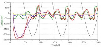
I include an illustration of simulated fundamental nulled voltage at the loudspeaker terminals of an Ariel, when driven by a D Self Blameless like amplifier that would normally rate such a 0.002% thd rating.
The black trace is output divided by 100 at 10kHz. (This is the propagation delayed trace from the blue - 8 ohm resistor loaded - nulling source)
The following simulated traces are all 'Ariel' loaded
The red trace is the basic amplifier error. (Output choke + Miller C.dom)
The mauve with series output choke but alternative stabilisation in place of C.dom.
The green without choke but with C.dom.
The yellow, no choke and no Miller C.dom. (Leading current back-emf induced crossover glitch still visible.)
Cheers ............. Graham.
Thank you for being like a Professor to our diyAudio Collegiate, in a thread that has remained unusually sane.
Fab asked me about the most appropriate bench tesing load, but then Mike hit on the head.
A resistor is a 'restricted special case' load. Dynamic loudspeakers load an amplifier quite differently, and electrostatics/Magneplanars completely differently again.
Amplifierguru cites making an amplifier capable of driving to any phase angle, but if that is done with a steady sinewave then yet again you will not observe fractional propagation delay/nfb induced errors that result from waveform/loudspeaker induced change.
From one half cycle to the next a dynamic loudspeaker system does not load an amplifier symmetrically, even if impedance compensated, because impedance compensation acts more directly whilst drivers and their back emfs act within dynamic energised time domains. Thus 'within any half cycle' plus 'within full cycles' errors for an amplifier that might acheive say 0.002% thd with the special case resistor are still going to be asymmetrically significant. As Wimms wrote, dynamic load changes alter the amplifier's linear response, and that is as it attempts to (propagation delay) correct the (delayed but often leading current back emf induced) errors it senses in real time.
Loudspeaker current is not only out of phase and modified by (time shifted) music waveform generated back emf, but can be as like having say 3 ohm loading during one half cycle to 15 the next. D Self did not cover this, and worse, he did not examine the effect of phase shifted back emf upon the operation of his rigorously 'stead state' examined bias/topology output stage arrangements.
JCX suggests multi-tone/intermod testing;
Francis suggests take up of the Gedlee testing proposals, where (if I remember correctly) higher generated components are given an error rating equivalent to the square of their order;
but I still think these examinations could mislead because they do not directly relate to propagation delayed nfb correction of music induced amplifier-loudspeaker back-emf interaction.
Amplifierguru. It is possible to design a 0.002% thd amplifier and yet it still not sound good !
In several posts I have shown my approximate circuit for the well known 'Ariel' loudspeaker which, by all accounts, works well the tube drive but rarely so with solid-state.
I include an illustration of simulated fundamental nulled voltage at the loudspeaker terminals of an Ariel, when driven by a D Self Blameless like amplifier that would normally rate such a 0.002% thd rating.
The black trace is output divided by 100 at 10kHz. (This is the propagation delayed trace from the blue - 8 ohm resistor loaded - nulling source)
The following simulated traces are all 'Ariel' loaded
The red trace is the basic amplifier error. (Output choke + Miller C.dom)
The mauve with series output choke but alternative stabilisation in place of C.dom.
The green without choke but with C.dom.
The yellow, no choke and no Miller C.dom. (Leading current back-emf induced crossover glitch still visible.)
Cheers ............. Graham.
Attachments
My point regarding comment 2). I know exactly the phenomonon you are talking about. It annoys me to no end. But I fear it won't go away even if "THD", "N", "IM", "TIM", "DIM" and all their cosins, real and imaginary, are eliminated. Only if someone finds a solution to the dynamic range problem including especially the purely psychological parts will the mush go away.
Regarding logarithmic compression, it absolutely is a form of amplitude distortion, but without most of the harmonics generated by other more brutal limiting techniques.
However, this thread has largely sidestepped frequency and phase distortion (no pun intended). Phase distortion can tend to be worse at higher frequencies, where it is believed to be less adible, but that is debatable. What is not debatable is the fact that frequency and phase distortion of a complex signal will change its waveform. At lower and mid frequencies, this can be quite audible, without any appreciable "THD".
Just food for thought...
Phase distortion, or really any sort of time domain distortion, is interesting. Again what is needed is to ground truth this in validated models of human hearing. The change from synchronous impulse detection to spectral band detection in the ear has been posited to occur at a frequency of at most 5kHz, and there is evidence that it starts to occur at more like 2.5kHz. Below this frequency the brain is measuring the period of the waveform, and detection of phase anomalies would appear to be quite possible. Limited one would imagine by a minimum time resolution. Above, and the brain can no longer maintain synchrony, and the mechanism for detection of phase anomalies goes away. This should present a useful metric to decide whether the phase anomalies in an amplifier matter. On the whole, you would want to consider the nature of the whole recording chain to decide. But maybe fast, or signal induced (therefore signal correlated) changes may be more obvious, and more prone to occur in a power amplifier.
Again, all such distortions are trivially measured, all that is needed is to choose the appropriate basis function for the analysis. An FFT can find phase changes trivially, except that everyone, so far, has thrown away the imaginary component of the transform when they look at the result.
Again, all such distortions are trivially measured, all that is needed is to choose the appropriate basis function for the analysis. An FFT can find phase changes trivially, except that everyone, so far, has thrown away the imaginary component of the transform when they look at the result.
Hi,
On jcx recommendation I went over to www.aes.org and
bought the Czerwinski paper "Multitone Testing of Sound
System Components..." JAES Vol 49, No. 11 online for $20.
This is really some paper. Thanks jcx.
The authors do a really good job of explaining how IM
is a much more significant problem then THD.
So is an amplifier with .002% THD good enough? Here is
what I got from the article...
It depends on three things:
1) the order of nonlinearity in the transfer function
2) the number of tones on the input
3) the amplitude of the input
So to paraphrase the article...if the system has hi-order
nonlinearity (even small amounts), this will cause a
multiplication of IM products. The effect doesn't appear in
single tone measurements (obviously).
To further paraphrase...
The second harmonic produced by a 4th order nonlinearity is
four times more sensitive to the level of the input signal than the
second harmonic produced by a 2nd order nonlinearity. This is
for two tones.
Also for two tones, the third harmonic produced by a 5th order
nonlinearity is six times more sensitive to input level than the
level of third harmonic produced by a 3rd order nonlinearity.
What this means is that if you are measuring .002% THD at
some reference level, and your system has hi order nonlinearities
then the figure will be much worse at 1.5 or 2x higher input levels.
Even if you are measuring .002% THD at max volume, there is
still a problem. This is as follows...
For a system with a 2nd order nonlinearity, for two
tones, the rms level of the intermodulation products is only 2
times higher than the rms level of the harmonic products
of those two tones.
For a 3rd order nonlinearity, and two tones, the rms level of
the intermodulation products are 4.2 times the rms level of all
harmonic products of those two tones.
For a system with a 3rd order nonlinearity and using 3 equal
tones, the rms level of the intermodulation products
are 9.2 times higher than the rms level of the harmonic
products alone.
Now these results are for relatively low order nonlinearities
and number of input tones. The IM increases a lot if the
system has higher order nonlinearities and also goes up as
the number of tones increase.
The key for IM is to have a transfer function with
as low a level of hi-order nonlinearities as possible.
Graham, this might be part of the effects you are seeing with
loudspeakers...when a transfer function with hi order
nonlinearities is subject to multiple tones on the input,
you have a situation guaranteed to generate lots of IM.
I believe that a lot of the manifestation of phase modulation
is to produce IM products as well.
I also would highly recommend this article 🙂
Mike
Can we have more threads like this one on DIYAudio? 😀 This is like it is supposed to be - polite debate, actual information. A big thanks to all participants for making it the joy it is to read.
Generally IM products mirror THD in most amplifier tests - so can you imagine the IM from a 0.2% amp tuned for its musicality to add warmth or some other 'correction' to the sound?
THD% and IM % generally track and IM <THD.
Since the maximum low level audibility of IM products is still in the 500 -3K peak in low level aural sensitivity and since feedback is very effective in minimising THD in this range it also does so for IM.
Erno Borbely (TAA 3/90) showed IM to be an order of magnitude below 20KHz THD at all levels for a number of typical circuits, hardly significant in a 0.002% 20KHz THD design! Robert Cordell obtained similar results.
To MFC : 
What can you say about Amplitudo Modulation (AM) and Frequency Modulation (FM) distortion that Mr. John Curl previously mentioned here?
What can you say about Amplitudo Modulation (AM) and Frequency Modulation (FM) distortion that Mr. John Curl previously mentioned here?
Regarding the example of the piano mentioned earlier, and why we tolerate real instruments' SPL much easier than reproduced SPLs:
I suspect it has to do with the "wall" of "spectral contamination" produced by the chain, including the speakers.
I mostly notice an absence of transparency when I listen to recorded piano as opposed to a real one. The tone sound less sharp, less clear. I suspect that the many low level distortion products taken together produce this effect, and make the reproduced sound more "broadband" than it originally was. So in effect it becomes more like a piano cum noise.
The human ear perceives loudness as an integrator, in other words, the average level produces most of the loudness impression, rather than the peak level. Now, this relates to time, but I could imagine that a similar thing happens in frequency - that a more broadband signal sounds "louder" (and of course, more "muffled") than a narrow band signal.
Does anyone have data on this bit of human hearing perception?
MBK
If your interested in all that perception stuff there's one I have "Perception of Phase Distortion in Anti-Alias Filters" by Pries and Bloom JAES V32n11 1984.
If your interested in all that perception stuff there's one I have "Perception of Phase Distortion in Anti-Alias Filters" by Pries and Bloom JAES V32n11 1984.
amplifierguru said:...Erno Borbely (TAA 3/90) showed IM to be an order of
magnitude below 20KHz THD at all levels for a number of typical
circuits, hardly significant in a 0.002% 20KHz THD design! Robert
Cordell obtained similar results.
Curious.
I don't have access to the first article. What is the
reference on the Cordell?
I wonder if they were using just two tones. That still should
produce more IM than THD though.
Time to break out some simulations. Sorry don't have access
to real equipment to measure this.
Mike
mfc
3 refs for Cordell
Another View of TIM Audio Feb 1980 (not so definitive0
Interface Intermodulation in amplifiers Wireless World Feb 1983
A Mosfet Amplifier with Error Correction AES preprint 1931 (D-9)
1982 Convention.
The third deals with SMPTE IM testing (60 and 6K 4:1)
also DIM (dynamic intermodulation distortion) using a 3.18K sq wave and 15K sinewave mixed 4:1 to test for TIM and filtered at 30KHz (DIM30) or 100KHz (DIM100).
He concluded: this amplifier employs substantial amounts of nfb (40dB at 20KHz) and 20KHz THD was the primary performance metric used in the design process. In recent years several new forms of distortion have been described, sometimes in the belief that they were caused by large amounts of nfb and that traditional measures of distortion would be ineffective in detecting them. Some of these beliefs have been shown to be unfounded.
Not having seen the article either, I can't comment specifically, but one needs to be very careful about drawing conclusions from the result.
If the IM is measured to be significantly lower than THD in a number of designs it does not follow that the two are linked, and that further reduction in THD will produce a commensurate drop in IM. A causative mechanism needs to be posited and verified - otherwise it is simply a data point. Indeed one would want to construct amplifiers with a defined mechanism for THD and IM creation, and verify the inter-relation of the two. Even then you would need to verify it for each mechanism. One would want a similar taxonomy of distortion mechanisms to Self's, but broken down into the nature of distortion production.
The creation IM and THD are different, so there is only a second order coupling between the two. NFB will clearly act to reduce both, up to a limit. This limit is likely different for each mechanism. In particular IM mechanisms in the feedback mechanism cannot be eliminated (as THD mechanisms cannot either.) If the feedback loop is the limiting component in distortion reduction, then the quantity of IM and THD will be quite unlinked in the limit.
So, to apply the idea that THD is always greater than IM in the limit of a very good THD result is very likely specious. You may have simply created a topology that has reduced all the THD mechanisms, but not only may you not have attacked all the IM mechanisms, you may indeed have exacerbated some, or even introduced more.
The above is simply a boilerplate reasoning about the applicability of results when there is insufficient knowledge. You could substitute almost anything into the idea. But I stand by the issue, there is no hard evidence, bar circumstantial, and certainly no mechanism, to suggest that a reduced THD reduces IM.
If your interested in all that perception stuff there's one I have "Perception of Phase Distortion in Anti-Alias Filters" by Pries and Bloom JAES V32n11 1984.
Phase distortion audibility is another interesting subject, though I meant more specifically the human perception of broadband versus narrowband stimulus of same SPL - because I suspect we can "pick" whether things are real or reproduced from the presence or absence of broadband hash. I also think that broadband hash presence may make a signal sound louder and more unpleasant, given same SPL.
Come to think of it, people claim tube amps sound louder at a given power than SS amps. Maybe related to higher broadband harmonics?
Francis,
I'm happy to conclude that IM is insignificant beside THD until I see something definitive published to the contrary. EVERY published curve of the two ALWAYS had the THD on top by 4 to 10 times!
MBK
It's often claimed that amps with substantial amounts of low order HD audition louder.
I'm happy to conclude that IM is insignificant beside THD until I see something definitive published to the contrary. EVERY published curve of the two ALWAYS had the THD on top by 4 to 10 times!
MBK
It's often claimed that amps with substantial amounts of low order HD audition louder.
Hi Leslie,
I'm not so sure that amplitude/phase distortion with frequency has been sidestepped; just not mentioned in this audio spectrum context.
Indeed you can have extremely low thd with a narrow bandwidth filter, but beyond its passband audible losses due to inadequate characteristics do become significant; and often start becoming audible at three times for low, and one third of for high turnover frequencies.
Hi Francis,
Yes. The time domain of a harmonic riding the back of a fundamental does become 'time' shifted, and thus phase shift does change the character of amplified sound.
With regard to our observation of phase (ie. wavefront timing) detection.
Surely the ear/brain is capable of recognising directional (ie. wavefront timing) information binaurally with a very high degree of accuracy even at 5kHz, and thus we are accurately capable of relative phase discrimination ?
What about moving the head to minimise the whistling effect of standing waves from 10>16kHz line timebases.
Hi Mike, (mfc)
Yes, not only are high order non-linearities part of the effect, but the real cause of all the IM too.
I am sure that Wimms in his 'Distortion Microscope' thread has also observed via simulation how the back-emfs developed by 'virtual' loudspeakers (which are less significant than those developed by real loudspeakers) are inductance delayed, influenced by capacitor charging, and return with significantly different frequency components due to different crossover network resonances and different driver plus air-spring resonances plus reflections etc.
What is fed back into an amplifier's other (nfb) input during a two or three cycle tone burst, when the amplifier under test is realistically loaded, is far more complex than can ever be realised with steady state testing, and I have found that for an amplifier to be least affected by loudspeaker back-emf it cannot perform optimally in the normal forward mode !!!!!
Anyone who sits optimising an amplifier for minimum distortion with a 'dummy' resistor load is NOT going to produce a design that will not be least reactive to loudspeaker system generated back-emfs.
Must head now. Back tonight.
Cheers ............. Graham.
With regard to our observation of phase (ie. wavefront timing) detection.
Surely the ear/brain is capable of recognising directional (ie. wavefront timing) information binaurally with a very high degree of accuracy even at 5kHz, and thus we are accurately capable of relative phase discrimination ?
What about moving the head to minimise the whistling effect of standing waves from 10>16kHz line timebases.
5kHz is a pretty high pitch. Only two octaves below the highest possible, and a bit over 4 octaves above middle C. That would be generally regarded as a piercingly high fundamental. Pretty much everything in life that we seem to worry about is below this, with only harmonics above. (Self fulfilling.) If the fundamental is well into the synchronous detection zone, the harmonics don't matter, they are simply added to the timbre by a separate mechanism.
Problem with looking at our ability to null out the time-base whistle is that the wavelength at these frequencies is about 2cm. If there are, as you suggest, standing waves, we are merely repositioning our ears somewhere else in the mess of nodes and anti-nodes, plus inserting our HRTF into the sound field to perturb the standing wave pattern. Try moving your head in the field with your finger in one ear. Can you still null it? Or try in an anechoic chamber.
- Status
- Not open for further replies.
- Home
- Amplifiers
- Solid State
- Nature of Distortion