the card has a built-in (actually screwed-on, removable shielding plate which covers the analog circuitry. i left it off, during the testing of the 49720 metal cans, since they were too tall, and i think the shield caused them to short out against their cases.
this was because i had premounted them in dip-8 sockets for pratice, and for easy switchability. i was hoping that the metal of the leads had a certain amount of memory, and once bent into the dip-8 pattern for a while, would stay that way, and eventually fit easily into the sound card's dip-8 sockets, without being installed into those sockets via another set of sockets.
this proved to be the sonic monster. i pulled out the socket-mounted opamps, and reinstalled them directly into the cards own sockets.
lo and behold, the sound improved in all the ways i was looking for. it is warmer, fuller, and more 'human' sounding -- i think coherent would be the right term to sum it up, without losing dynamics or detail. the ambience and the acoustic are now integrated with the musical performance, rather than being somehow seperate.
i'll keep burning them in and will report back after they've had another day of playing, and see what develops.
i am also going to put two 49710s onto a browndog adaptor, and try that for the output position as well, once my hakko esd-safe soldering station arrives tomorrow.
once i've made that comparison, i'll put the shield plate back on, and leave it alone and enjoy the music from the sound card--
it is a very good card, and responds well to proper opamp rolling.
thanks to both of you for the suggestions!
best regards,
Mark
mark -- saw your last reply after i'd posted my discovery about the extra sockets. perhaps you can email me about the shielding ideas when you have a spare moment.
i'm pretty sure i still have one of your damping disks floating around here in my collection of audiophilia.
i'll let you know about the 49710s once i get them done, and will also try them in the prodigy sound card as well. once i have a handle on their sound, i'll post on the relevant boards at head-fi and audio asylum as well, as i;ve been documenting my foray into computer audio there as well.
Fzman,
Just a quick warning, which I am sure you already know, but the cans are connected to the negative rail!
Do you have one of the old cd damping disks or one of the 20 lb EMA damping/isolation plates?
Also multiple sockets will mess with the sound on these parts. Already verified that myself quite awhile ago. One socket max or soldered in is the best for your final version.
Mark / audioman54
if i still have one, it would be the disk, although i auditoned the plates, and liked them very much.
the double-sockets are a no-no, and where the cause of the sonic anomilies. i don't think soldering is an option, but down the road, i may think about making the opamps permanent, by soldering them into the board's sockets.
first step now is to solder two 49710s to the browndog and see if that makes an improvement over the single 49720.
then shielding.......
best,
Mark
jackinnj said:Is this the new "correct" comp circuit for the LME49810?
An externally hosted image should be here but it was not working when we last tested it.
Jack,
Have a look at AN-1850 page 13 for the comp circuit - sorry, didn't have time to make a nice drawing like yours... It shows the circuit a bit differently. Is An-1850 for something different?
thanks,
Ken
Hi Klewis,
AN-1850 was written for the LME49730 which is the FET driver in the series. The added circuit shown (which is not in AN-1850) was designed by Bob Pease for the LM4702 and the LME49811 (the 811 is a mono 4702 with a minor tweek). The circuit that is "added" in the posted drawing is actually a "noise gain compensation" circuit. (I had never seen one before Bob showed it to me!) It is required for the 4702 and the LME49811.
Best Regards,
Mark / Audioman54
audioman54 said:Hi Klewis,
AN-1850 was written for the LME49730 which is the FET driver in the series. The added circuit shown (which is not in AN-1850) was designed by Bob Pease for the LM4702 and the LME49811 (the 811 is a mono 4702 with a minor tweek). The circuit that is "added" in the posted drawing is actually a "noise gain compensation" circuit. (I had never seen one before Bob showed it to me!) It is required for the 4702 and the LME49811.
Best Regards,
Mark / Audioman54
Mark -- did you tweak the amp in AN-1490 for the new compensation circuit? If so, what was your impression.
I just got in another Crown DC300 for an amp-ectomy.
Hi Jack,
That circuit was designed for the amp in AN-1490! It solved a stability problem in hard clipping and improved the sound quality a bit. Again, it is a "must do" for the LM4702 and LME49811. It was not required on the LME49710 which is a totally different animal.
Mark / audioman54
That circuit was designed for the amp in AN-1490! It solved a stability problem in hard clipping and improved the sound quality a bit. Again, it is a "must do" for the LM4702 and LME49811. It was not required on the LME49710 which is a totally different animal.
Mark / audioman54
Hi Mark,
Thanks for sharing all your wonderful knowledge with us here.
Just a quick question. I use the LM4562 and OPA2107 (TI 🙄 ) in an active crossover. Can I use the LME49713 as a drop in replacement? (The circuit was initially intended for OPA2134, but I found the former better)
Thanks,
West
Thanks for sharing all your wonderful knowledge with us here.
Just a quick question. I use the LM4562 and OPA2107 (TI 🙄 ) in an active crossover. Can I use the LME49713 as a drop in replacement? (The circuit was initially intended for OPA2134, but I found the former better)
Thanks,
West
Hi West,
The LME49720/4562 is probably your best choice for most crossover circuits. (Rmember to use the metal cans for best sonice results!) However if you send me your schematic I can be more specific.
Current feedback opamps require a set value of feedback resistor. 1.5k in the case of the LME39713. Also the 49713's only come in singles.
Mark / Audioman54
The LME49713 is a current feedback opamp -- so it takes a bit of care and feeding --whubbard said:Hi Mark,
Thanks for sharing all your wonderful knowledge with us here.
Just a quick question. I use the LM4562 and OPA2107 (TI 🙄 ) in an active crossover. Can I use the LME49713 as a drop in replacement? (The circuit was initially intended for OPA2134, but I found the former better)
Thanks,
West
audioman,
i reinstalled the metal can 49720s in my sound card-- directly inbto the card's sockets, without the carriers i was cheating with. sounds much better, and has fleshed out with some 50 hours of burn.
since i am horribly curious, i soldered two metal can 49710s into a browndog adapter, and put that in the output position on the card (i don't think they'd fit in the i/v positions, and each dip carries a single channel (which you hinted would not improve from having seperate packages anyway).
the adaptor does not fit as deeply into the socket as i'd like, since there are some small box-shaped caps in the way, but the singles do sound a slight bit better. if i decide to keep them in, i may try to figure out how to remout those caps on the other side of the card, or bend them over if their leads are long enough, or can be "extended".
any thoughts?
best,
Mark
audioman54 said:Hi Klewis,
AN-1850 was written for the LME49730 which is the FET driver in the series. The added circuit shown (which is not in AN-1850) was designed by Bob Pease for the LM4702 and the LME49811 (the 811 is a mono 4702 with a minor tweek). The circuit that is "added" in the posted drawing is actually a "noise gain compensation" circuit. (I had never seen one before Bob showed it to me!) It is required for the 4702 and the LME49811.
Best Regards,
Mark / Audioman54
Mark,
I really appreciate your comments and tips, they've been quite helpful.
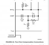
I don't want to be a pest about this, but, this is what is shown in AN-1850 called a two pole compensation circuit. (I hope the image shows up)
I'm currently stuffing a preamp board with the LME49720's with a dc servo - I switched to the metal can variety on your recommendation and am really looking forward to hearing the results. I've also built the power regulators around the LME49860, that up and running - it shows less ripple on the scope compared to LM317 regulators.
Regards,
Ken
Attachments
Hi Ken,
Yes the circuit shown in the AN-1850 ap note is a two pole comp circuit but it is different than the one show in your previous posting. In that one the comp cap (Cc) goes from the comp pin to Biasm pin and then the resistor cap combo (3k/75pf) that is the noise gain cancellation circuit also connects to the comp pin but then it is connected directly to ground. The two pole comp is quite different.
Does that make sense?
Mark
Hi Mark,
Hope the job hunting is showing some positive results. It's a bad time for everyone looking for new positions.
In the listening tests of the LME498xx family were there any tests done running the LME498xx in inverting mode?
I'm in the final circuit design / board layout stage and have a LME49710 chip at the input doing balanced to single end conversion. It would be quite easy to drive the inverting input from the LME49710 if there were any benefits of said connection.
Thanks,
Gary
Hi GaryP,
The 49710 VFB opamp is the perfect choice to do the diff to single ended stage in your design. I prefer the sound of the 49713 but CFB opamps do not make the best diff to single ended ckts because the plus and minus inputs are different circuits/impedances internally.
With either the LM4702 or LME49811 I have listened to them both ways (and even did some single blind tests with others as subjects at National) and inverting wins every time! The 49810 is a little different animal but it is very close to the 811 sonically (with 10x the current out!) so you could use it if you need a higher power amplifer. My rule of thumb was 811 for all amps under 300W and 49810 for everything over that. Also the 810 has some nice extra features the 811 does not have like a clipping indicator output. I use the 811 in all my power amplifiers at home now and my 2 Krell KSA 200S amps are no longer used.
With regards to job searching I just got news from another semi company, just around the corner from National, that they received my resume but are not hiring anytime soon. Dang! Early retirement and full time playing with new audio circuits? That would be great...but the not having any income to buy parts for those audio projects keeps getting in the way!
Best Regards,
Mark
Also Jackinnj, the LME parts will work with single supplies. Use very high quality DC blocking caps though! (Polystyrene 1st choice, Polyprop next).
Thanks for the reply Mark,
I think I'll go with the 49811. The amp will be on the low power side for the SS world, most likely in the 50 watt range for continuous power with high peak capability.
With my listening habits and speakers that put out 95dB per watt I don't need that much power. The reference amp in the system now is a 20 watt class A amp of my own design. The earlier version of the amp is on my web page if you want to look (SS Tabor)
The donor chassis is a late 70's Hitachi HA-5700, one of the early MOSFET amps. Provides +/-12V for the low voltage, +/-45V for the outputs and +/-52V for the input stage.
We are going to try using 2 pair of NJL4281D/NJL4302D ThermalTrak transistors for the outputs and use MJE15032/MJE15033 for the drivers.
Should be an interesting experiment to see how the low voltage hi current amp can compare to the reference amp.
Thanks again for your input.
Gary
Gary P's DIY page
- Status
- Not open for further replies.
- Home
- Amplifiers
- Solid State
- National opamp inflation