Hi all
I bought a ZERO ZONE Naim NAP200 clone but the materials that included differ from the values marked on the board. So instead of 0.22Ω resistors it contains 0,39Ω. The seller on ebay say to adjust the voltage to 5mV across the 0.39Ω (R13) resistor so the idle current calculated to 5/0.39=12.82mA. It is correct? because I read on some threads that this current must be about 22mA so I have to change the voltage from 5mV to 8-10mV. It's OK?
Best Regards
Spiros
O.39 ohm resistors are just plain wrong unless you fit 2 in parallel in the same location as each 0.22ohm type. Check the quantity supplied to see if that was the intention, noting that there is a third 0.22ohm resistor, same 2W, located in the output path to the speaker connector of each channel.
If the quantity is only the same as shown on the PCB (i.e. 6 x 0.22 ohm resistors in total) and the power rating is the same as the specified types, the dissipation is doubled and they will fail before full power is reached. Fit correct 0.22 ohm resistors which you can buy from electronic suppliers in most major cities or from distributors like Farnell Element 14, RS, Mouser etc.
The bias setting is not critical above 5 mV across either 0.22 ohm emitter/collector resistor or 10mV across both resistors in series. The recommended setting is 7.5mV or 15mV across both. I suggest you don't run the amplifier at full power unless an aluminium heat spreader bar (25-30 x 5mm section) is fitted (with thermal grease) between the power transistors and case bottom plate, as in the original design.
Last edited:
Hi Ian
not the seller supplied 0.39 Ohm instead of 0.22 Ohm so I have to replace them. I have find to a local supplier 0.22 Ohm/3W Viishay. Are they OK?
For the colant I will use a very good cooper plate.
Thanks for instructions
Regards
Spiros
not the seller supplied 0.39 Ohm instead of 0.22 Ohm so I have to replace them. I have find to a local supplier 0.22 Ohm/3W Viishay. Are they OK?
For the colant I will use a very good cooper plate.
Thanks for instructions
Regards
Spiros
I don't know the specific type of resistor you mean to use but 3W types in either metal film or wire wound form should be fine. First, check that the length of the resistor when the leads are bent will still fit between the PCB holes. You need to add at least 3mm to the resistor length to estimate this. Set the resistors a little distance, say 4mm above the board, to improve cooling and reduce discolouration of the PCB when they become warm.
A copper plate is excellent if thick enough to spread the heat evenly to the bottom plate which should be 3mm thick or more, to conduct the heat to the rest of the chassis. I may have confused you by advising the use of thermal grease but that must only be used between the bottom of the copper plate and the chassis bottom plate. The transistors are fine with just their silicone pads.
Good luck with your build and setting up - it's a fabulous sounding clone if the semis are the genuine, correct types.
Hi Ian, do you know of any populated boards for sale that have been known to have original transistors and correct layout? Thanks
As indicated often in the NAP140 thread, our desire for perfection is seldom met in Chinese clone kits (not at affordable prices, at least). You can modify kits and finished boards with appropriate parts if you can find good substitutes or even the originals, as are necessary in the case of the original Diodes Inc. VAS transistors. That will get you much closer but you can forget about buying finished boards that include special components that have to be imported to China. It won't happen unless it is for a very large quantity of kits.
The better approach is the very good NAP200 clone where the PCB is almost identical to the original model and when first released by Caowei, the semis were actually originals or very close and it sounded great. However, beware now of the semis and small capacitor substitutes supplied by ZeroZone who is about the only kit supplier now. The assembly and PCB mounting isn't easy to do either but the rewards can be well worth the effort of doing it right. The parts issues, a schematic and BOM too are all covered at intervals in the NAP140 clone thread from #1752 in late 2015.
The better approach is the very good NAP200 clone where the PCB is almost identical to the original model and when first released by Caowei, the semis were actually originals or very close and it sounded great. However, beware now of the semis and small capacitor substitutes supplied by ZeroZone who is about the only kit supplier now. The assembly and PCB mounting isn't easy to do either but the rewards can be well worth the effort of doing it right. The parts issues, a schematic and BOM too are all covered at intervals in the NAP140 clone thread from #1752 in late 2015.

Ian one more question.
The kit includes some silver mica capacitors 5% (two with wrong values, 43p instead of 39p and 50p instead of 100p). I need to replace them with a polystyrene or not?
The kit includes some silver mica capacitors 5% (two with wrong values, 43p instead of 39p and 50p instead of 100p). I need to replace them with a polystyrene or not?
There's probably going to be a big problem sourcing the correct 39pF polystyrene capacitors with ≥ 80V rating. A kit supplier would not send you expensive silvered mica types unless he couldn't buy the specified polystyrene film/foil type in the correct values either.
I would not be too concerned with using a 43pF value in place of 39pF as the compensation cap. To make certain there is no problem, you need to check that the amplifier is not oscillating. Without instruments, you cannot hear or see the oscillation but there are side effects like the amplifier getting hot even when the bias is low and there is no signal. Take care as this can destroy an amplifier if ignored.
Here are a couple of sources for polystyrene capacitors: the first is in the UK and as usual, very expensive but they are allegedly new stock. There are only a few useful values for solid state circuits in their catalogue though. Polystyrene Capacitors | Hifi Collective
This source in the US is cheap and has many useful NOS values. https://www.surplussales.com/Capacitors/Poly-Unelco.html
I'm sure you can find more but these are obsolete products and you can't expect to get exactly the type you need for popular kits in Europe, like Naim clones.
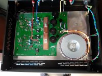
It looks quite good too. Congratulations!
A few things you might like to do when able:
1)The electrolytic caps appear to be the supplied NOVER brand. When you can afford it, replace with either original Naim spec. type or Kendiel (Italy) equivalents, There is certain to be some improvement.
2) The low bias current of NAP models means that the amplifier runs quite cool without signal so the chassis should be closed off to allow it to warm up to operating temperature evenly and fairly quickly, so that bias settles and is controlled correctly. The Vbe multiplier transistors are not attached to anything and rely on heat transfer by air and their proximity to the bottom of the case to allow correct and consistent bias tracking with temperature. If cool air flows in from below the chassis, bias may not track properly. Naim uses 3mm thick aluminium, closed boxes but perhaps a small amount of ventilation at the sides is a good idea in a warm climate like Greece.
3)You seem to be using a thin gauge aluminium case and this won't conduct heat very fast or far from the transistors. Perhaps this can be fixed by fitting a large, 3mm thick aluminium plate between the heat spreader bar and the chassis to improve this.
4.I think you are using the flat copper bar to clamp the power transistors as well as spread the heat below. The clamp bar should not bend at all, so that it applies even pressure across the top of the transistors. Otherwise, they may overheat because the maximum pressure is close to the clamp bolt and likely nothing at the other ends. I would add a piece of channel section aluminium on top of, or in place of the flat bar. 15 x 15 mm or deeper, heavy gauge aluminium channel may be rigid enough See pictures of the original NAP200 which show how it's done.
Hi Ian
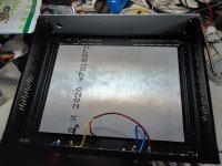
below the thin (1.5mm) aluminium board there is a thick aluminium slab (260x350x8mm) in a tight thermal contact with the enclosure, the thin board and the cooper bar.
On the board's surface I placed the amplifier board with 6mm spacers.
The amp runs quite cool without signal and the diffusion of temperature is fast and evenly.
I have run in full power on 8 Ohm dummy load with fantastic thermal behavior
Surely I will replace the capacitors.
The clamp cooper bar is 5mm very strong with thick washer and NOT bend.
Maybe I will add this thick channel like Naim
Ian
Thanks for all
Spiros
Well done. It seems you really have taken care of most likely problems that occur when the volume is turned up to full power. Don't forget about too much cooling air flow though. Enjoy!
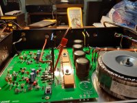
Looks great. All the right capacitors in the right orientation too.
Did you go for a transformer with electrostatic shield?
Did you go for a transformer with electrostatic shield?
Unfortunately, you would have to unwind it first! The electrostatic shield sits in between the primary and secondary windings and Naim connects it to mains earth. The idea is to foil the inter-winding capacitance so mains noise doesn't pass to the secondary.
- Home
- Amplifiers
- Solid State
- NAP200 Clone materials