Hacker
Im building the 5 channel power-amp for my "home cinema" setup based on HTPC with have Good HD audio card used with Denon A1D as 5 channel amplifier sound great but wont fit in the furniture from Old Charm depth is 430mm ( Denon sports 550mm depth and 60 pounds in weight!) have tried 6 channel Rotel didn't like the sound anemic and boring ( use pair of Naim Credo as front ) Having electronic engineer background decide to build a panel like 5 channel amplifier with will be in-build in to back board of existing old coffer providing good ventilation for heat-sink and living loads of space for htpc and media to store inside.
I have done some research and your The HackerNAP amp looks more like finished and well balanced design to all compact power amplifiers I have found on the net would you please estimate 5 sets of this amp including parts with input stage transistors matched to one +10HFE gain to ensure perfect DC output balance?
Nap clone pcb
Neutrality have you print any of this pcb's ? Ill love to join inn for 6 of thouse
Those points have been adressed a few days ago, just havent gotten around to post it here. 🙂
As you probably know most PCB layout design work is usually a WIP, with continous tweaking taking place. From first draft to the final version a lot of stuff can and do happen. 🙂
The 2 x FE gnd, 2 x OP gnd, zobel gnd and signal gnd are all seperated.
Regarding R23, there will be a inductor, just havent put it on the schematic.
Neutrality have you print any of this pcb's ? Ill love to join inn for 6 of thouse
Rectifiers, OP transistors and Front end Xformer
Dear fellows, first : all the best for you and family in this new year
I am in the process of building a pair of Hacker NAPs and have 3 concerns :
1) Fast rectifiers
I have On Semi MSRF1560G and MUR1560G rectifiers rated 600V/15A in stock and want to know if they are suitable fre the OP or the FE PSU, or both ? What should the LQA30T300 and LQA16T300 improve ?
2) Output transistors (TR9 & TR10)
I have On Semi MJL21194G at hand and the only difference I notice from the recommended MJW21194G is the packaing (TO-264 vs TO-247 resp). Am I right ?
3) Trannies
I will use Selectronic R-Core 36-0-36/300VA transformers for the OP PSU but I have difficulties to find 44-0-44/50VA toroïds for the Front-End PSU. Where can I source them ? Did you have them specially wired ?
TIA for your help,
Hervé, Grenoble, France
hd38, would not it make sense to use R-core (i.e. apparently better) transformers for the FE as well?
Alex.
Alex.
Hi Hd38,
As Alex (Hi Alex!) suggests I have found R Cores to be better for the front end in particular. The OP PSU is less fussy but I have used a single 432VA 29-0-29 as OP Tranny and was very pleased with its sound. I have used 2 X 24-0-24 Selectronic low wattage types for the FE and just connected them up to give 48-0-48v. The extra volts can be easily dropped with resistors in series with the power rails between the caps.
Higher voltage low wattage toroids and R Cores are generally hard to find and this was my optimum solution.
I found that the LQA rectifiers gave a slightly cleaner sound as they are very low storage rectifiers and switch more cleanly as a result, but I used choke regulation and snubbers which may have made this more obvious. I would suggest that you try the rectifiers that you have to start with and consider the LQA's as a future upgrade once things are running. Fit them so you can easily remove them without making them unusable.
Hope that helps
John
Last edited:
Thanks Alex and John for your handy replies.
There are 14, 30 and 50 VA models, which is the lowest wattage model usable for a stereo amp with 2 FE modules (I lack of room !) ?
There are 14, 30 and 50 VA models, which is the lowest wattage model usable for a stereo amp with 2 FE modules (I lack of room !) ?
Thanks Alex and John for your handy replies.
There are 14, 30 and 50 VA models, which is the lowest wattage model usable for a stereo amp with 2 FE modules (I lack of room !) ?
The amp FE will function with any of these models as the front end only draws about 10mA per rail on each channel which if you use two 24-0-24 volt transformers equates to about 1 watt off each rail for a stereo amp.
However (unless you are choke regulating) the short term charging currents will be much higher, maybe up to an amp, depending upon the caps you use and the transformer resistance. You can do an easy simulation to see this on Ben Duncans PSUD (PSU Designer) software which is free if you google it. You can focus in on the diode currents and see how high the current spikes go. I have found that the larger the transformer you use here the better the sound, and the returns from this approach diminish somewhere between 50 and 100VA. So if you have the space try to go for the 50VA models, even if it means just having one front end PSU for both channels.
John
Great idea. I did use Duncan PSUD in the past for valve projects.The amp FE will function with any of these models as the front end only draws about 10mA per rail on each channel which if you use two 24-0-24 volt transformers equates to about 1 watt off each rail for a stereo amp.
However (unless you are choke regulating) the short term charging currents will be much higher, maybe up to an amp, depending upon the caps you use and the transformer resistance. You can do an easy simulation to see this on Ben Duncans PSUD (PSU Designer) software which is free if you google it. You can focus in on the diode currents and see how high the current spikes go. I have found that the larger the transformer you use here the better the sound, and the returns from this approach diminish somewhere between 50 and 100VA. So if you have the space try to go for the 50VA models, even if it means just having one front end PSU for both channels.
John
BTW my caps for the FE are Kendeil 1000uF/80V and the resistors are 4R7/3W (value has moved to 47R in the latest BOM I think).
Hence in one word : bigger "iron" is to be prefered even at the cost of diaphony ?
Great idea. I did use Duncan PSUD in the past for valve projects.
BTW my caps for the FE are Kendeil 1000uF/80V and the resistors are 4R7/3W (value has moved to 47R in the latest BOM I think).
Hence in one word : bigger "iron" is to be prefered even at the cost of diaphony ?
Nicely put. That pretty well sums up what I have found. I've sent a little email to Leigh which might help you a little as well.
John
Hi there,
I'm the guy that put together the original HackerNAP/HackerCAP project. It's based on the Naim NAP and Avondale NCC200 circuits, with some Acoustica modifications and other bits n bobs gleaned from the Internet. I don't claim any credit for designing those circuits or components, only for amalgamating them in one place for one design.
I did, however, layout the HackerNAP (and the corresponding power supply, the HackerCAP) PCBs very painstakingly. One of the design goals was to think very carefully about separating the power supplies for the front-end and for the output stage. Among those considerations was the arrangement and design of the 0V configuration, which is not very straightforward. The separate power supplies are also highly customised to account for the different needs of the output stage and the front end.
The design that you've come up with is, at best, compromised compared to the original, and I'm afraid your schematic/PCB has at least one error: you have placed R23 (a 15R) directly in series with the amp output. This will not work without the corresponding output inductor! The 15R is supposed to be in parallel with the output inductor and is merely there to stop ringing. Without the inductor, you're going to (at best) ruin the sound of the amp. In all likelihood you'll quickly release the Magic Smoke.
The layout of your board also negates many (most!) of the benefits that the amp & PSU design were designed to bring to the table, especially the grounding/PSU layout, which is the amp's major design feature and was designed to alleviate some of the problems associated with the NAP/NCC designs. For example, the shared 0V returns on your board are going to do you no favours (eg. the Zobel is connected directly to the signal 0V; the signal 0V is also slung right between the power 0Vs, which will modulate the signal; the front-end and output stage 0Vs share a common PCB track, etc etc etc ), and honestly there are so many compromises with your board layout that if you haven't already made it, I suggest you stop right now and do some redesign work.
To help you along, please take a look at the build manual and schematic for the original HackerNAP. It's available for free here: HackerNAP project page. I urge you to read that page carefully before proceeding. In fact, don't just read the web page - download the actual build manual because it contains much more information, photos, diagrams, close-ups, etc etc.
You'll also find the PCB Gerber files, bill of materials, and schematic freely downloadable. This is an open-source project and you are of course welcome to do with it as you wish; I would, however, urge you to reconsider the design that you are embarking on because it is a big step backwards over the original. If you do go ahead with this design I would be grateful if you called it something other than a HackerNAP 😉
Having said all of that, please feel free to ask any questions. I'll do my best to answer, and hopefully we can come up with something that allows you to use TO3 devices without compromising the HackerNAP design. Hell, I might even add another variant of the PCB to incorporate TO3 devices if there's any interest from other folks.
Cheers,
Carl
Anyone has any idea where to get the latest gerber files, BoM and schematics for both HackerNAP and HackerCAP? The links above don't work anymore
Thanks
Do
You could begin your search at Pinkfishmedia, the home of Naim tweaking and where the information, manual and files were posted in an archived thread opened 7th April 2011. There have been later threads but the project ended 3 years ago.
Or....a quick Google finds this site (no surprises) where the manual and all files are now indexed for download: hackernap.com
Hyperlinks make it difficult to navigate the site but that address lands you at the parent directory and the index of available docs, gerbers. manual etc.
Or....a quick Google finds this site (no surprises) where the manual and all files are now indexed for download: hackernap.com
Hyperlinks make it difficult to navigate the site but that address lands you at the parent directory and the index of available docs, gerbers. manual etc.
Thanks Ian
Was at the Hackernap site prior to giving a "bump" and as you've
mentioned the hyperlinks does make it difficult.I thought the links might be dead as all download attempts failed.Will try from a desktop as it seems downloads does not work from that site on my cellphone.
Regards
phunk
Was at the Hackernap site prior to giving a "bump" and as you've
mentioned the hyperlinks does make it difficult.I thought the links might be dead as all download attempts failed.Will try from a desktop as it seems downloads does not work from that site on my cellphone.
Regards
phunk
Last edited:
I have no problems downloading but you may have other issues with reading the downloads unless you have the appropriate software installed. Just about every document type seems to need some obscure reader, converter or modifier program that costs more than it should in comparison to free readers that have been around some years now.
I have finally downloaded them via a desktop computer.
Pc software or hardware is not a problem as I do repairs on both as well(since the early 1990's).
Regards
phunk
.
Pc software or hardware is not a problem as I do repairs on both as well(since the early 1990's).
Regards
phunk
.
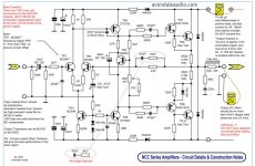
100mA or 100mV? DC Offset is a voltage and at that low level is really only an aesthetic issue. i.e. it wont hurt normal, room size loudspeakers and you wont hear it. However, have you understood the second instruction in black print, at the top, left side of the schematic?
In the manufacture of the real Naim amplifiers and presumably Avondale's versions, the LTP transistors are tested for hFE and selected to provide an appropriate mis-match. That can re-balance the output of the intentionally unbalanced LTP (input stage transistor pair). In other words, it does not have a pot. Like the Naim assembly workers, you are required to select the most suitable semis from a mixed stock of parts instead of adjusting a pot. That forces the bias current in each transistor to have a more equal current in the idle state.
Hope the build works out fine for you 🙂
Last edited:
I have also built the NCC200, used matched transistors, but in 20 transistors could not find a difference in hFE of 10% (all of the transistors I bought had exactly the same hFE). Is there another way to adjust the DC offset (now it is 82mV and stated in the diagram was less than 50mV). And another question - what is the recommended power voltage?
- Home
- Amplifiers
- Solid State
- NAP140/NCC200 Clone with PSU