I received my kit over the Christmas-New year break here. I had a look at the overlay and compared the few different sections like the current source type used for the LTP. The circuit of each amplifier is really very little different from that of the 1970s NAP250 module. There is no necessity for all circuits to be identical for all models, is there?
Bear in mind that there was more than one Naim amplifier model and it was necessary to accommodate the various supply voltages, gain and power levels. I would expect some changes in ideas over 25 years too. Nait fanatics will also be aware that their low power models skipped a few features of the larger models completely.
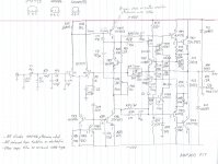
The 2 x 330R resistors are indeed parallel, Ruwe. Obviously there was a need for a value between 150 and 180R but many small companies have a policy of only designing with E6 or E12 resistor values, for example. That's not an issue for mass produced products today but I'd say these NAP models were too expensive for high sales volumes. I'm not aware of any examples here in Oz but there are probably a few around.
The PCB is the important feature of this design for DIY constructors. You won't see much as an improvement bycomparing schematics because the real benefit, compared to doing whatever you think is good enough, lies in the grounding layout for the whole amplifier. At least you can replicate exactly what was intended here. Everything revolves around the single, brilliantly photo-replicated PCB, so any trace errors would also be on the original pattern. Build it as the PCB dictates and see how it turns out. Obviously, others have already successfully done so.
Bear in mind that there was more than one Naim amplifier model and it was necessary to accommodate the various supply voltages, gain and power levels. I would expect some changes in ideas over 25 years too. Nait fanatics will also be aware that their low power models skipped a few features of the larger models completely.
The 2 x 330R resistors are indeed parallel, Ruwe. Obviously there was a need for a value between 150 and 180R but many small companies have a policy of only designing with E6 or E12 resistor values, for example. That's not an issue for mass produced products today but I'd say these NAP models were too expensive for high sales volumes. I'm not aware of any examples here in Oz but there are probably a few around.
The PCB is the important feature of this design for DIY constructors. You won't see much as an improvement bycomparing schematics because the real benefit, compared to doing whatever you think is good enough, lies in the grounding layout for the whole amplifier. At least you can replicate exactly what was intended here. Everything revolves around the single, brilliantly photo-replicated PCB, so any trace errors would also be on the original pattern. Build it as the PCB dictates and see how it turns out. Obviously, others have already successfully done so.
I guess that the higher HFE for TR1 compared to TR2 still apply in this circuit?
It's the same idea. I guess most accurate to say the Re of each is different. Some thought has gone into this. Maybe a real NAP 250 was on hand to clone. It is nothing like the Avondale.
Hopefully Andrew T would like to say if running this much TR1+2 current would please him or if he ever tried it? It seems to me to be totally OK to do this. If anyone has a DC offset number for this amp I would be interested. For this alone, this is a very interesting version. I think it's originator isn't convinced about this part of the amplifer being a pure I to V ( into TR4 base ) converter like myself. One thread I was reading was convinced high slew rates were proven high quality requirements. Not one person could give a reason. Mostly I was told it is true because the best in the world do it. The maths say even 0.5 V/uS should do real music and 100 watts. This usually is uprated to 2V/uS and finally 6 V/uS worst case. The converstions suggest 50V/uS as just about OK. Now there must be some truth in it. My feeling is they have discovered a hard work way of saying the I to V into the TR4 VAS needs plenty of current.
D.Self shows balanced operating conditions in his "Blameless" and shows highish LTP tail current.
High tail current along with emitter degeneration brings back the gm of the input stage, thus maintaining the open loop gain that would otherwise be lost.
The BIG advantage of this is discussed by Leach in his Lo Tim papers, reduced distortion for high amplitude, high speed signals.
An additional advantage can be much increased slewing capability. There is more current available to drive the capacitance of the VAS/TIS stage.
Thanks Andrew. Do you have a link?
Does anyone have a simple slewing calculation for amps like this ? I am not sure how I do it is correct. I presume we calculate for the worst example when sourcing or sinking current. If the VAS was a true I to V converter we would simply say the feedback current equals the drive current at a virual earth I suppose?
Does anyone have a simple slewing calculation for amps like this ? I am not sure how I do it is correct. I presume we calculate for the worst example when sourcing or sinking current. If the VAS was a true I to V converter we would simply say the feedback current equals the drive current at a virual earth I suppose?
I'll try post #1759 again (now that some people have the kit):
Any thoughts on the grounding scheme?
Since it's a dual mono, I would normally not connect the 2 channels together and would float them from the chassis.
The 200/Clone connects the power stars together and these are daisy chained to the signal star (see the track + links between the middle 2 smoothing caps and track round the top edge of the pcb). Looks a bit odd to me, but Naim generally do know their onions when it comes to grounding. Do they connect the signal star to chassis??
All exposed conductive parts must connect to the protected chassis.....................I would normally not connect the 2 channels together and would float them from the chassis.......................Do they connect the signal star to chassis??
Don't worry your little head Andrew. I generally use split bobbin mains transformers and the chassis is connected to mains earth. On the odd occasion when I use toroids, I use ground lift resistors with antiparallel diodes to earthed chassis to ensure safety.
Maybe we can discuss the NAP200 clone instead of you worrying about my safety, whether or not I can balance an LTP and if I am going to fry my tweeters. It's getting a bit tiresome to be honest.
Maybe we can discuss the NAP200 clone instead of you worrying about my safety, whether or not I can balance an LTP and if I am going to fry my tweeters. It's getting a bit tiresome to be honest.
And the power transformer rating? I read that it was probably a 300VA with dual 28VCT and a 26VCT for the preamp. What is the recommended current capacity per secondary for the amp?
I'll probably need to order two Plitron transformers to have two secondaries connected with a CT. I just want to be sure of the correct transformer to order.
Thanks
SB
I'll probably need to order two Plitron transformers to have two secondaries connected with a CT. I just want to be sure of the correct transformer to order.
Thanks
SB
Ok last attempt to ask the question. Any comments on the way Naim has done the grounding indicated by the wiggly blue line?:
An externally hosted image should be here but it was not working when we last tested it.
Last edited:
Ok last attempt to ask the question. Any comments on the way Naim has done the grounding indicated by the wiggly blue line?:
Hi Dave,
I looked at the pictures here:
Black BOX ?clone Naim NAP200 Amplifier KIT DIY Power AMP KIT 75W 75W | eBay
I can't say I know it as a fact, it's not clearly visible, but I think they ground the board to the chassis through the input jacks, which is also the way recommended by D. Self. Then you can see on the AC receptacle the small green wire that connect the chassis to earth ground. There might be another grounding wire going in the transformer from the receptacle, but most likely it's just a grounded magnetic shield.
If you look closely at the pics of the inside of the original NAP 200 and clone here and elsewhere, you can see there is no connection to the chassis other than at the Mains (protective) earth and input cable connector shell. Naim used a 4 pin DIN connector which includes connections for a +24V preamp supply, so signal ground is common to both channels and to the 24V supply ground. It is carried through to input star ground, the same as all early NAPs and shown in the connection illustrations for wiring up the clone, which surely is plain enough for all to see....Do they connect the signal star to chassis??

In other words, everything on the secondary side of the transformer floats above chassis ground, as with all older Naim products I've encountered and many others. It may not be ideal by contemporary standards but this neither a new or conventional product.
And the power transformer rating? I read that it was probably a 300VA with dual 28VCT and a 26VCT for the preamp. What is the recommended current capacity per secondary for the amp?
I'll probably need to order two Plitron transformers to have two secondaries connected with a CT. I just want to be sure of the correct transformer to order.
Thanks
SB
I usually say twice the rated power if you can. If it was 250 watt total 4R then 500 VA looks good. If a strict 8 ohms load even 250 VA would seem OK. In theory even 100VA could work. I doubt it would sound good ( 50 % efficient, 6:1 creast factor, 70 watts 8R real music x 2 ). It wouldn't be happy. I think Quad used 300VA to give 2 x 100 watts in the 405. It was considered the limit of how small one should go. Were it not for how the Quad current limiting worked it would have been undersized for 4 ohms.
This advice is a bit like how much chocolate in a chocolate cake. Within reason as much as you can.
Anyone worked out the slew rate for this amp?
....I'll probably need to order two Plitron transformers to have two secondaries connected with a CT. I just want to be sure of the correct transformer to order....
Assuming there is a stock 28 + 28VAC transformer available, it would probably be in a standard ISO rating series like 80, 160, 300VA. With many DIY designs I've either built, fixed or just heard about, 2 x 160VA is an economical size that will supply the current for domestic use of any conventional amplifier but to deliver full power continuously into low impedance speakers, 2 x 225 VA would be the better choice from the Plitron range. As I read their online catalogue though, the nearest standard voltage is 25V which would give you 35VDC rails and a bit of redesigning of the amplifier to suit that.
Be aware that the VI limiters are fancy dual slope types in this model and well worth keeping, considering it is already there and no other protection is. However, it only works correctly at the specified supply voltages 😉
Ive weighed up the options locally for me, here in Oz, where 28V transformers are no longer stock items. I think a custom 400VA quad wound toroid will be a fair option, despite the high, one-off cost.
Last edited:
In other words, everything on the secondary side of the transformer floats above chassis ground, as with all older Naim products I've encountered and many others. It may not be ideal by contemporary standards but this neither a new or conventional product.
Very good point, Ian. That reminded me that I read some time ago in a Naim product brochure that the grounding of the audio circuits in an all-Naim system happens in the source. Use in no-all-Naim system has never been their concern. People who buy commercial Naim gear have almost religious dedication to them and wouldn't buy from other brands anyway.
Last edited:
But the Plitron have 115V primaries, here in Quebec, Canada we have 120V in the socket. Plitron always give me around 1.11x the specified voltage because of that. Hence the 25V model will give me a nice 27.75, or 28V 😉
Two 225VA transformers will equal to a comfortable 450VA transformer with dual CT secondaries. I'll supply the preamp supply with a smaller transformer.
Two 225VA transformers will equal to a comfortable 450VA transformer with dual CT secondaries. I'll supply the preamp supply with a smaller transformer.
Last edited:
That looks fine. Naim used larger transformers for the pre amps. Usually 160 VA costs slightly more than lets say 50 VA. Worth a thought.
Robin the service guy at Naim said they didn't know where zero volts was exactly on their amps. He joked somewhere up a cable. He was refering to the floating situation. As far as I remember everything floated. The cases were grounded for safety where a transformer was used, That would mean the DIN and speaker negative floated. When doing that sometimes a 100 nF and 100 R are connected in paralell from PSU 0V to chassis on the power amp only. I have no idea if Naim did that.
Robin the service guy at Naim said they didn't know where zero volts was exactly on their amps. He joked somewhere up a cable. He was refering to the floating situation. As far as I remember everything floated. The cases were grounded for safety where a transformer was used, That would mean the DIN and speaker negative floated. When doing that sometimes a 100 nF and 100 R are connected in paralell from PSU 0V to chassis on the power amp only. I have no idea if Naim did that.
A 300VA 26Vct transformer will have a current rating of 300/26 = 11.54AacAnd the power transformer rating? I read that it was probably a 300VA with dual 28VCT and a 26VCT for the preamp. What is the recommended current capacity per secondary for the amp?
I'll probably need to order two Plitron transformers to have two secondaries connected with a CT. I just want to be sure of the correct transformer to order.
Thanks
SB
But I don't think you meant to type 26Vct. I think you meant 26-0-26Vac which is 52V centre tapped. The current rating of a 300VA 52V ct is 300/52 = 5.76Aac.
A Power Amplifier for domestic duty will work pretty well with a transformer VA that is one to two times the total maximum power output.But the Plitron have 115V primaries, here in Quebec, Canada we have 120V in the socket. Plitron always give me around 1.11x the specified voltage because of that. Hence the 25V model will give me a nice 27.75, or 28V 😉
Two 225VA transformers will equal to a comfortable 450VA transformer with dual CT secondaries. I'll supply the preamp supply with a smaller transformer.
i.e. if you have a 40W+40W into 8+8ohms amplifier then the total maximum output is 80W and that will operate pretty well with a transformer rated anywhere from 80VA to 160VA.
The NAP140 is a name given to the Power Amplifier that has a total maximum output into 4r0 test load of 140W, i.e. 70+70W into 4+4ohms resistive. That would operate pretty well with a 140VA to 280VA transformer.
I don't know if the NAP140 is rated to operate with 4ohms speakers. It will certainly drive 8ohms speakers reliably and the maximum output will be around 40+40W, on the UK 240Vac, which often runs @ 245Vac in the evening when we listen the maximum power could well be around 50+50W into 8+8ohms.
Your 115:25+25Vac transformer when operated on 120Vac supply will give ~26.1+26.1Vac. It is NOT 25*1.11 times.
I think you are adding in the transformer regulation to the 4.35% extra you would measure in changing from 115 to 120Vac.
i.e if you have a 115:25+25Vac 7% regulation transformer and measure it when fed with 120Vac, the output voltage will be 120/115*25 * (1+7%) = 120/115*25*1.07 = 27.9Vac when there is no load. That is NOT equivalent to a 28+28Vac transformer.
A 115:28+28Vac 7% regulation transformer when fed with 115Vac will have an opencircuit output of 28*1.07 = ~30Vac. Clearly quite different from 27.9Vac.
Last edited:
I think you may be measuring unloaded transformer voltages. Secondary winding voltages are specified at the rated current, so when there is no load, the transformer "regulation" will permit voltages up to about 8% high for a typical 225VA transformer. Consider also that the line voltage difference is really only 4% high, so the secondary voltage can't be more than 26V at the rated current. If you measure 27.7V with an unloaded 25V transformer, a similar 28V transformer will measure around 30.8V unloaded. Allowing that regulation permits 2.2V drop, you would have a closer 28.6 VAC when it is critical at high current peaks, so that VI limiting remains effective protection.....Plitron always give me around 1.11x the specified voltage because of that. Hence the 25V model will give me a nice 27.75, or 28V....
Have a look at this article: Transformers Part 2 - Beginners' Guide to Electronics
Last edited:
- Home
- Amplifiers
- Solid State
- NAP-140 Clone Amp Kit on eBay